
Heart valve assembly and methods for using them

Active Publication Date: 2005-07-28
MEDTRONIC INC
View PDF30 Cites 319 Cited by
  • Summary
  • Abstract
  • Description
  • Claims
  • Application Information

AI Technical Summary

Benefits of technology

[0007] The present invention is directed to heart valves that may be implanted into a patient, and, more particularly, to multip

Problems solved by technology

Because of their circular cross-sections, sewing rings that are implanted may not optimally fit the biological annulus into which a valve may be implanted.
As a result, natural blood hemodynamics through and around the valve may be impaired, resulting in clotting, possible emboli production, and eventual calcification of the valve structure.
As patients grow, particularly pediatric patients, the leaflets of a valve may no longer be properly sized to fit the annulus.
Leaflets may also calcify or otherwise foul and need to be replaced.
To replace the leaflets on a single-piece prosthetic valve, the entire valve must be removed, which may cause trauma to the annulus and jeopardize implantation of a replacement valve.
Further, it may be difficult to work around and through leaflets of a valve to attach a leaflet-laden valve, possibly damaging the leaflets and extending the length of the valve replacement procedure.
Sewing rings can also be tedious and time consuming to secure to a valve orifice.
To assemble multiple component heart valves, one component has to be sewn into another in vivo, resulting in a complex and time consuming process.
The complexity of the procedure also provides a greater opportunity for mistakes and requires a patient to be on cardiopulmonary bypass for a lengthy period.
Multiple piece heart valves also typically require a significant amount of handling during implantation, potentially exposing the delicate leaflets to damage before or during in vivo implantation.
Additionally, orientation of the components of a multiple piece heart valve is generally not defined by the device, making the implantation of the second piece of the valve less intuitive.
The surgeon must align the components of the valve during in vivo assembly when limited access can impair dexterity and the fragile valve components are at risk of being damaged.
Also, known multiple piece valves lack sufficient mechanical safeguards to insure that the surgeon will properly orient or secure the valve components.
Once implanted, multiple component heart valves can have problems with the components fitting each other in a secure and stable manner.
Improper fit can cause mechanical stress and hemodynamic anomalies leading to clotting, dislodgement or valve failure.

Method used


Image

  • Heart valve assembly and methods for using them
  • Heart valve assembly and methods for using them
  • Heart valve assembly and methods for using them

Examples


Embodiment Construction

1. Multiple-Component Heart Valve Assemblies

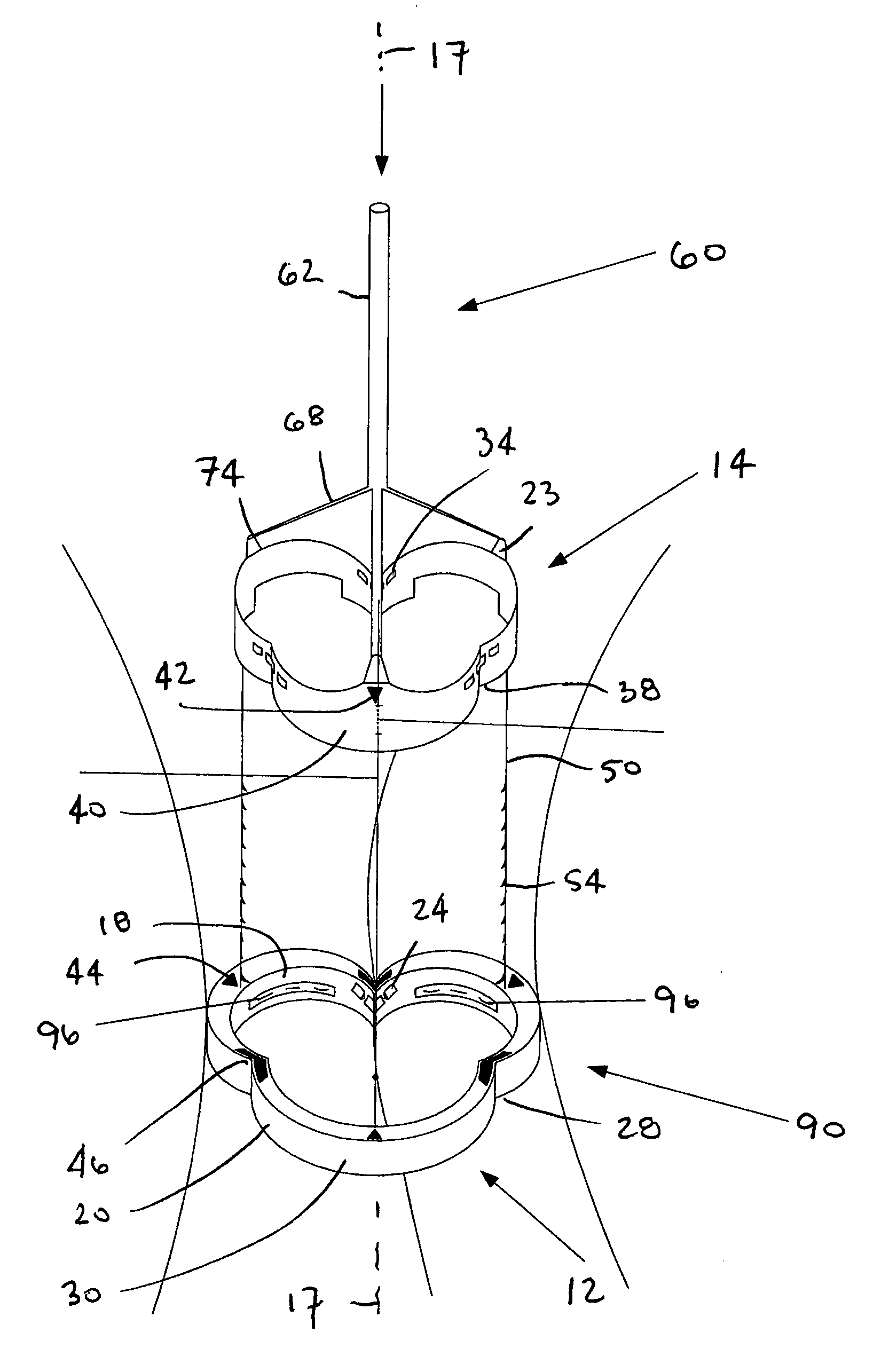
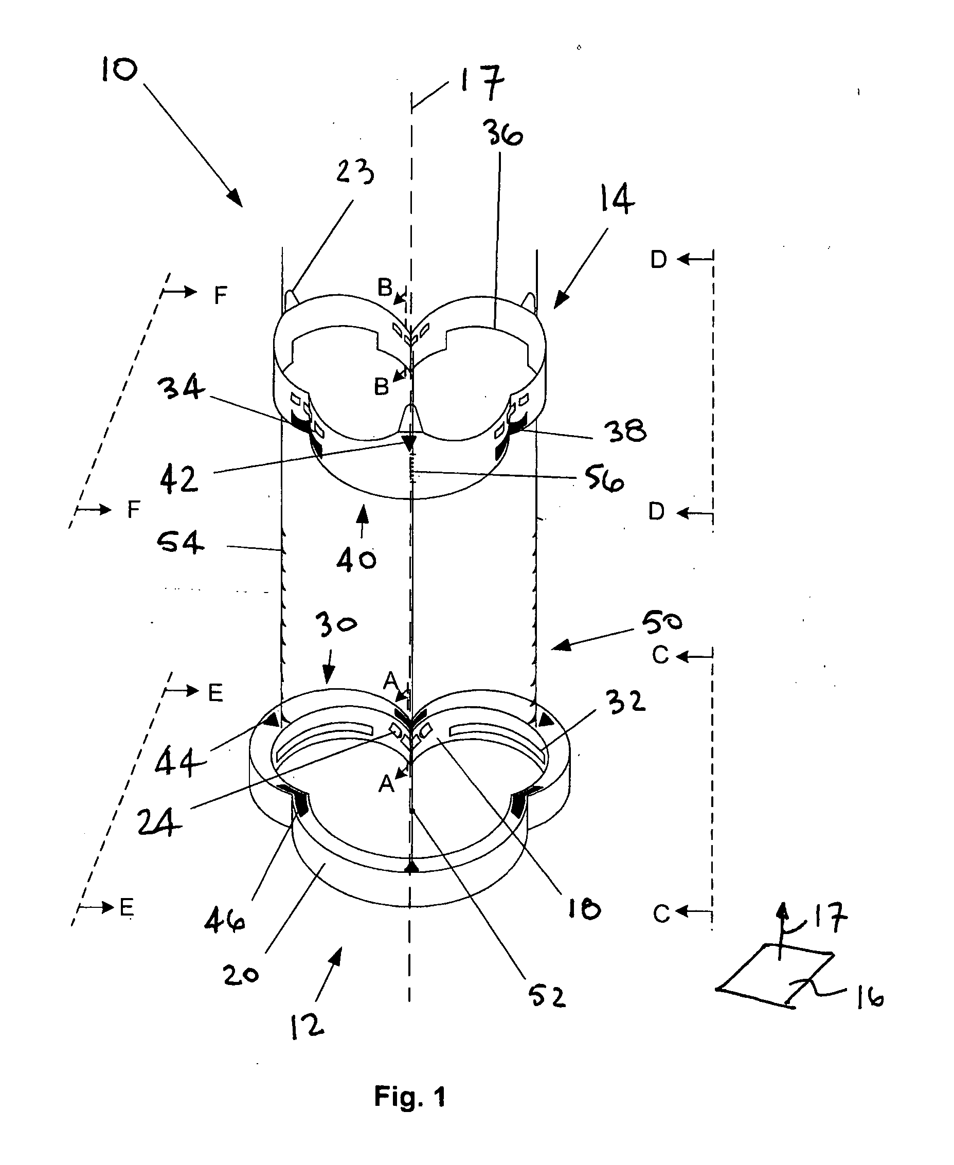
[0032] Turning to the drawings, FIG. 1 illustrates a heart valve assembly 10 that generally includes a base member 12 and a valve member or “crown”14. As described further below, the base member 12 and / or crown 14 may include one or more connectors for attaching the crown 14 to the base 12 and / or one or more guides for facilitating aligning and / or connecting the crown 14 with the base 12.

[0033] The base member 12 may be a generally annular shaped body lying in a plane 16, thereby defining a longitudinal axis 17 substantially orthogonal to the plane 16. The base member 12 may have a noncircular shape within the plane, such as a multi-lobular shape. Preferably, the base member 12 has a tri-lobular shape, i.e., including three lobes 30 separated by three cusps 28, corresponding generally to a cross-section of a biological annulus within which the base member 12 may be implanted, as explained further below. It will be appreciated that the b...


PUM


Abstract

A heart valve assembly includes a base including a multi-lobular annular shape within a plane, a valve member or other annular body including a multi-lobular shape complementary to the shape of the base, and cooperating connectors on the base and the annular body for connecting the annular body to the base. The base includes an anchoring ring, and a flexible cuff for attaching the base to a biological annulus. The base and the annular body include guides for aligning their multi-lobular shapes, e.g., visual, tactile, or other markers, or tethers that extend from the base that are slidable through the annular body. During use, the base is attached to a biological annulus, the annular body is directed adjacent the annulus, oriented such that the multi-lobular shape of the annular body valve member is aligned with the base, and the annular body is attached to the base.

Description

FIELD OF THE INVENTION [0001] The present invention relates generally to heart valves that may be implanted into a patient, and, more particularly, to multiple component heart valve assemblies that may be assembled together, and to apparatus and methods for making and implanting them. BACKGROUND [0002] Prosthetic heart valves can replace defective human valves in patients. Prosthetic valves commonly include sewing rings, suture cuffs, or rings that are attached to and extend around the outer circumference of the prosthetic valve orifice. Because of their circular cross-sections, sewing rings that are implanted may not optimally fit the biological annulus into which a valve may be implanted. As a result, natural blood hemodynamics through and around the valve may be impaired, resulting in clotting, possible emboli production, and eventual calcification of the valve structure. [0003] As patients grow, particularly pediatric patients, the leaflets of a valve may no longer be properly s...

Claims


Application Information

Patent Timeline
IPC IPC(8): A61F2/24
CPCA61F2/2409A61F2/2412A61F2250/0097A61F2250/0098A61F2250/006
Inventor DREWS, MICHAEL J.GURSKIS, DONNELL W.BACICH, STEVEN R.
Owner MEDTRONIC INC
Learn More