Method and apparatus for balancing a motor vehicle wheel

Active Publication Date: 2005-07-28
SNAP ON EQUIP
View PDF13 Cites 13 Cited by
  • Summary
  • Abstract
  • Description
  • Claims
  • Application Information

AI Technical Summary

Benefits of technology

[0011] The optical scanning beam can further serve for marking the balancing positions when the wheel to be balanced is moved into the appropriate angular position. In that case, a change in the axial position of one or both balancing planes can be implemented by the optical scanning beam being displaced or pivoted. In that case, the point of impingement of the optical scanning beam lies in the corrected balancing plane. That modification can be effected by the operator. An evaluation device of the balancing machine then re-calculates the angular position and size of the balancing weight, for the new balancing plane. It is possible to provide optimum positioning of the balancing weight on the surface of the rim.
[0012] The data related to the detected contour fe

Problems solved by technology

Contour features that are not suitable for fixing balancing weights include steps in the rim surface o

Method used


Image

  • Method and apparatus for balancing a motor vehicle wheel
  • Method and apparatus for balancing a motor vehicle wheel
  • Method and apparatus for balancing a motor vehicle wheel

Examples


Embodiment Construction

[0017] In the following description, for the purposes of explanation, numerous specific details are set forth in order to provide a thorough understanding of the present disclosure. It will be apparent, however, to one skilled in the art that the present disclosure may be practiced without these specific details. In other instances, well-known structures and devices are shown in block diagram form in order to avoid unnecessarily obscuring the present disclosure.

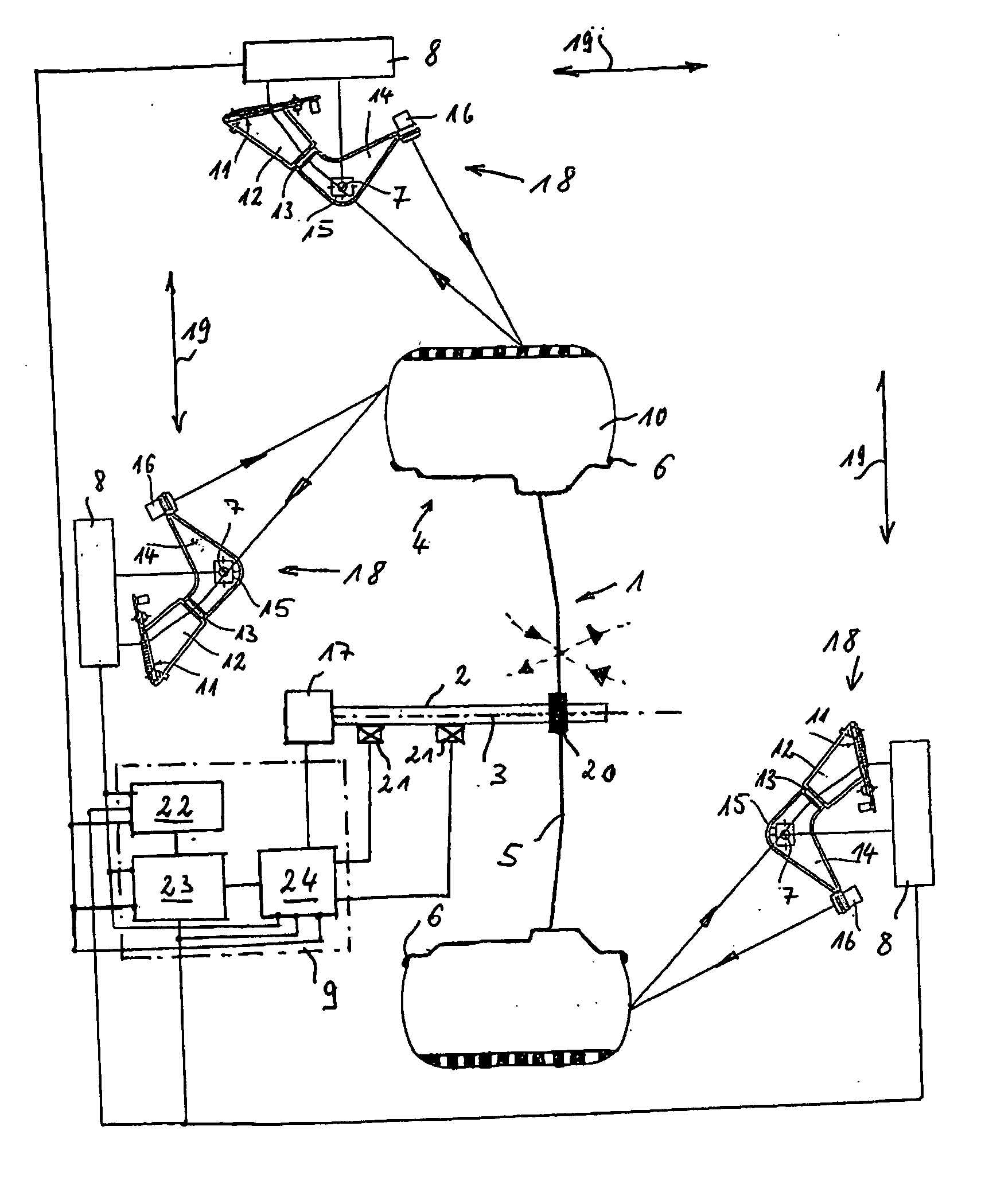
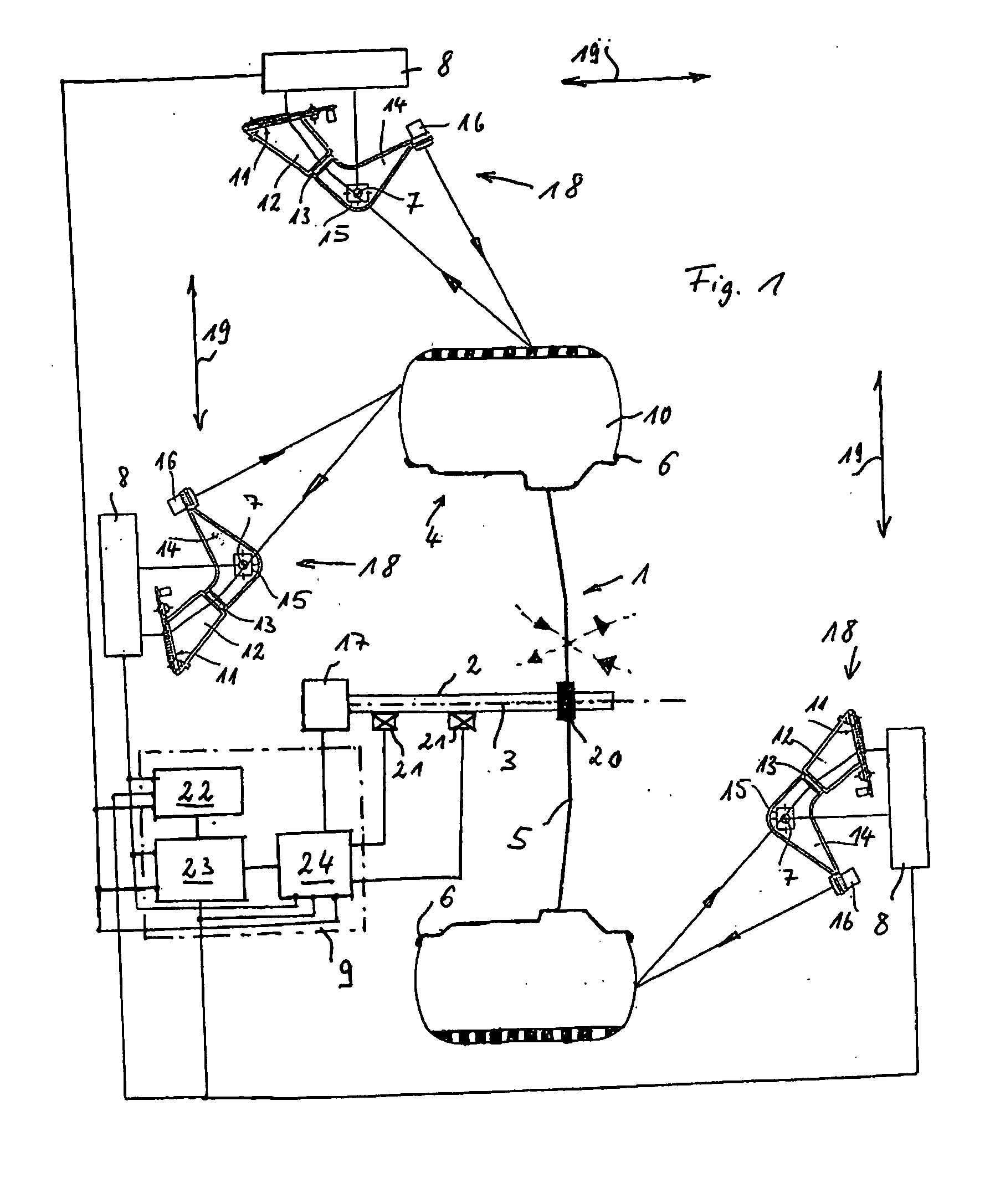
[0018]FIG. 1 shows an exemplary system for carrying out the wheel balancing process described in this disclosure. In FIG. 1, a vehicle wheel 1 has a wheel disc portion 5 and a rim 4 fixed to the periphery of the wheel disc portion 5. A pneumatic tire 10 is mounted on the rim 4. Tire beads are supported in known manner at rim flanges 6 of the rim 4.

[0019] The vehicle wheel 1 is fixed in known manner to a measuring shaft 2 of a wheel balancing machine (not shown), and is rotatably supported on a rotation axis defined by the m...


PUM


Abstract

A method and apparatus for balancing a motor vehicle wheel, in which after an unbalance measuring operation, at least one balancing weight is attached to at least one balancing plane in a given angular position of the rim of the motor vehicle wheel. The rim surface is scanned to determine its contour features. The contour features are compared to reference contour features of stored rim surfaces, to determine matching rim types and at least one balancing plane associated with the best match.

Description

RELATED APPLICATIONS [0001] This application is related to a co-pending patent application Ser. No. ______, titled “METHOD AND APPARATUS FOR OPTICALLY SCANNING A PNEUMATIC TIRE OF A VEHICLE WHEEL,” filed concurrently herewith; a co-pending patent application Ser. No. ______, entitled “METHOD AND APPARATUS FOR BALANCING A MOTOR VEHICLE WHEEL,” filed concurrently herewith; and a co-pending patent application Ser. No. ______, entitled “METHOD AND APPARATUS FOR OPTICALLY SCANNING A VEHICLE WHEEL,” filed concurrently herewith. All of the applications are commonly assigned to the assignee of this application, and are incorporated herein by reference in their entireties.FIELD OF THE DISCLOSURE [0002] This disclosure concerns a method and an apparatus for balancing a motor vehicle wheel, in which after an unbalance measuring operation, at least one balancing weight is attached to at least one balancing plane in a given angular position of the rim of the motor vehicle wheel. BACKGROUND AND S...

Claims


Application Information

Patent Timeline
IPC IPC(8): G01M1/22G01M1/38G01M3/32G01M17/02
CPCG01M1/225G01M17/027G01M3/3218
Inventor BRAGHIROLI, FRANCESCO
Owner SNAP ON EQUIP
Why Eureka
Try Eureka