
Steel pipe pole base and reinforcing method thereof

a technology of steel pipe and pole base, which is applied in the direction of buildings, buildings, buildings, etc., can solve the problems of deterioration of strength at the portions, proof of stress and fatigue properties, and likely structural defects in boxing welded portions at the upper end portions of the ribs, etc., to achieve relaxation of stress concentration, imposing residual compressive stress, and high energy

Inactive Publication Date: 2005-08-04
NIPPON STEEL CORP
View PDF12 Cites 18 Cited by
  • Summary
  • Abstract
  • Description
  • Claims
  • Application Information

AI Technical Summary

Benefits of technology

[0007] The present invention has been established for solving the aforementioned conventional problems and providing a steel pipe pole base and a reinforcing method of the steel pipe pole base, those making it possible to: suppress the deterioration of strength in the vicinity of the weld toe of a rib even when a repeated bending moment is imposed on the steel pipe pole; and prevent the deterioration of the proof stress and fatigue property of a boxing welded portion at the upper end portion of the rib. The gist of the present invention is as follows:
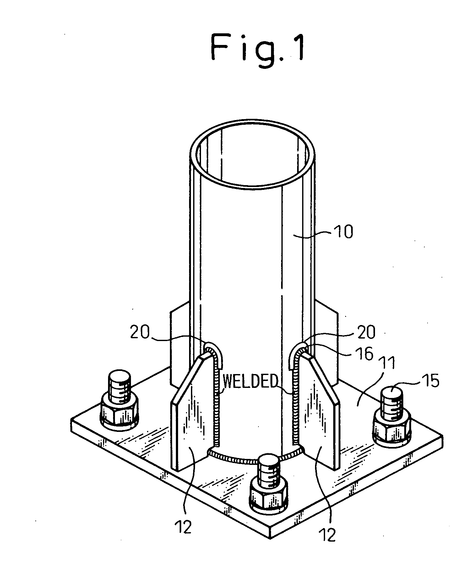
[0014] As mentioned above, in the present invention, peening treatment is applied by ultrasonic vibration to the weld toes of inverted-U or inverted-V shaped ribs formed by bending the upper end portions of tabular ribs welded to a steel pipe pole base in the form of a T-joint. The method employed for the peening treatment is a method wherein a cylindrical tool is ultrasonicalls vibrated in the axis direction, the tip of the vibrating cylindrical tool is applied to the surface of an objective metal and, by so doing, the surface is made concave. This method makes it possible to strengthen a steel pipe pole base by imposing a high level energy on a metal surface, thus producing plastic deformation, relaxing stress concentration, and imposing residual compressive stress on a weld toe.
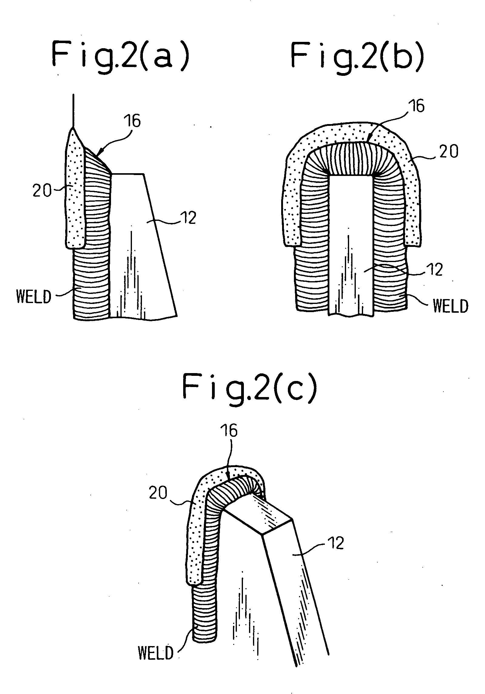
[0015] Further, in the present invention, by employing inverted-U or inverted-V shaped ribs as mentioned above, the upper end portions of the ribs are liberated from the principal stress direction of a steel pipe pole to a direction perpendicular to the principal stress direction and the rigidity of the rib upper end portions is lowered. As a result of this, it is possible to considerably relax stress concentration produced at weld toes, when bending stress is imposed on a steel pipe pole, and also the residual tensile stress caused by welding heat.
[0016] Furthermore, in the present invention, a peening treatment is applied to the weld toes of ribs by ultrasonic vibration. The method employed for the peening treatment is a method wherein a cylindrical tool is ultrasonically vibrated in the axis direction, the tip of the vibrating cylindrical tool is applied to the surface of an objective metal, and by so doing the surface is concaved. In consequence, a high level energy is imposed on the weld toes, plastic deformation is produced, and residual compressive stress is imposed. For this reason, the weld toes that have been the weak points of a steel pipe pole base are further strengthened and therefore it becomes possible to suppress the deterioration of strength at the weld toes of ribs and prevent the deterioration of the proof stress and the fatigue property, of boxing welded portions at the upper end portions of the ribs, even when a repeated bending moment is imposed on a steel pipe pole.

Problems solved by technology

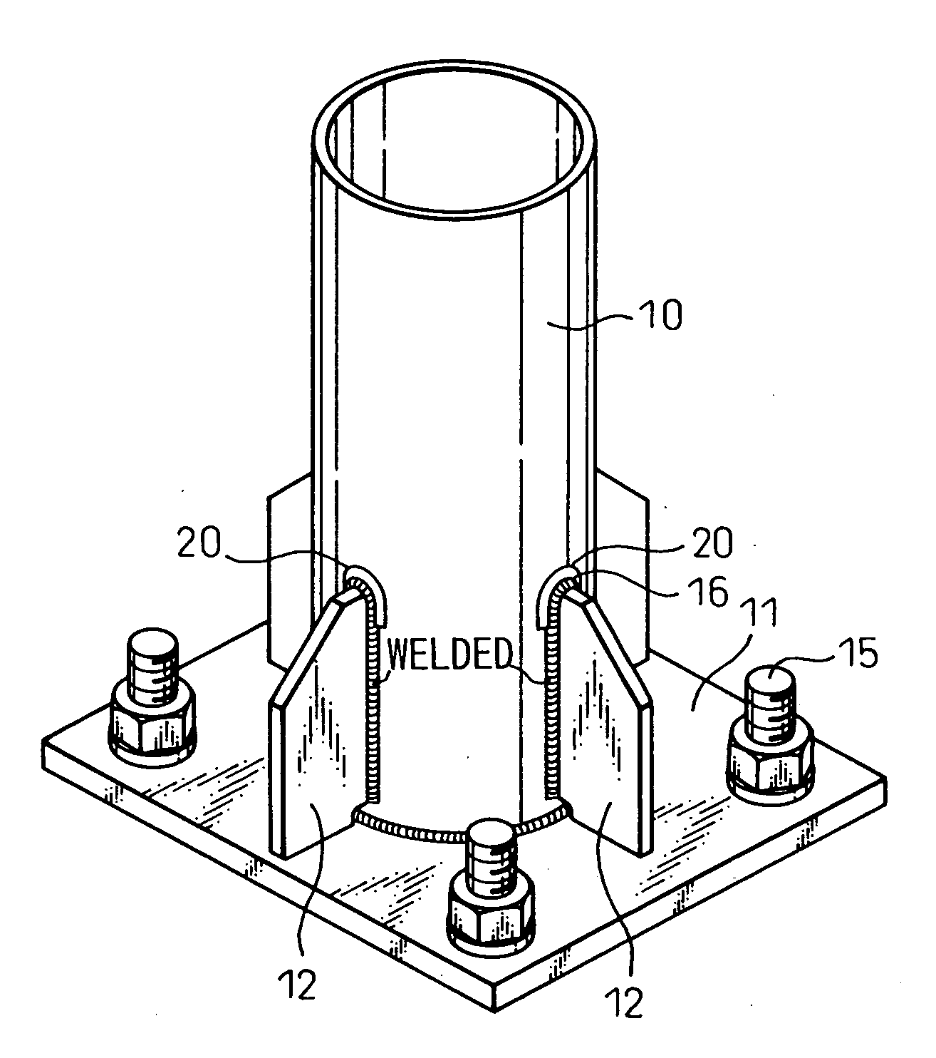
However, in a conventional steel pipe pole base as described above, there has been a danger that, when a bending moment is imposed on a steel pipe pole 10 due to wind, vibration or the like, a large stress concentrates on the steel pipe pole 10 near the weld toes 16 of ribs 12 and, as a consequence, the strength at the portions deteriorates due to the repeated stress.
Another problem has been that structural defects are likely to occur in the boxing welded portions at the upper end portions of the ribs 12 as a result of the combined effect of the residual tensile stress and the material degradation of the heat-affected zones caused by welding heat and to cause the proof stress and the fatigue property to deteriorate.
Those problems are common to joint structures in which reinforcing ribs are welded to structural members in the form of a T-joint and, in view of this, the Japanese Society of Steel Construction points out, in “Guidelines for Fatigue Design of Steel Structures and Its Interpretation”, that a joint in which a gusset is welded by fillet welding adversely affects the proof stress and fatigue property of a steel member and therefore attention has to be paid to the design of structures.

Method used


Image

  • Steel pipe pole base and reinforcing method thereof
  • Steel pipe pole base and reinforcing method thereof
  • Steel pipe pole base and reinforcing method thereof

Examples


example 1

[0045] Fatigue strength tests were carried out by imposing repeated tensile stress on partial specimens around steel pipe ribs having the construction shown in FIG. 1. The material used for both the steel pipes and the ribs was SM 490. The fatigue property of the conventional construction having as-welded ribs as shown in FIG. 10 corresponded to the E to D grades of the design life curves in the “Railway Bridge Design Guideline” as shown by the black round marks in FIG. 7. On the contrary, the fatigue property of the invention construction wherein peening treatment was applied to weld toes by ultrasonic vibration markedly improved up to the grade B or higher of the design life curves as shown by the white round marks in the figure. Here, the amplitude of the tool tip was 40 μm and the frequency thereof was 30 kHz.

[0046] Further, when peening treatment was applied by ultrasonic vibration while a load for applying tensile stress was imposed on a steel pipe pole base, the fatigue prop...

example 2

[0047] Fatigue strength tests were carried out by using a test device and imposing repeated tensile stress on the steel pipe pole bases according to the present invention as shown in FIGS. 3 and 4. The material used for both the steel pipes and the ribs was SM 490. In comparison, fatigue strength tests were carried out by imposing repeated tensile stress on partial specimens around steel pipe base ribs having the construction shown in FIG. 10. As a result, the fatigue property of the conventional construction shown in FIG. 10 corresponded to the E to D grades of the design life curves in the “Railway Bridge Design Guideline” as shown by the black round marks in FIG. 8. On the contrary, the fatigue property of the invention construction markedly improved up to the grade A of the design life curves as shown by the white round marks in the figure. Here, the amplitude of the tool tip was 40 μm and the frequency thereof was 30 kHz.

[0048] Further, when peening treatment was applied by ul...


PUM

PropertyMeasurementUnit
diameteraaaaaaaaaa
diameteraaaaaaaaaa
diameteraaaaaaaaaa

Abstract

The present invention: provides a steel pipe pole base and a method for reinforcing the steel pipe pole base that do not allow the strength to lower in the vicinity of the weld toe of a rib even in the event of applying repeated bending moment; and is characterized by forming peening processed portions 20 by ultrasonic vibration at the weld toes 16 of tabular ribs 12 welded to the base of a steel pipe pole 10 in the form of a T-joint or the weld toes of inverted-U shaped ribs 13 or inverted-V shaped ribs 14, the ribs being bent at the upper end portions, welded to the base of a steel pipe pole 10 in the form of a T-joint. Preferable treatment conditions are 20 to 50 μm in amplitude and 10 to 50 kHz in frequency. In particular, the present invention makes it possible to remarkably improve the fatigue property because stress concentration is relaxed by the synergetic effect of bending the upper end portions 16 of the ribs 13 and applying a peening treatment.

Description

BACKGROUND OF THE INVENTION [0001] 1. Field of the Invention [0002] The present invention relates to a steel pipe pole base and a reinforcing method of the steel pipe pole base for, for example, fixing a steel pipe pole such as a street light support pole, a road sign support pole and the like to a skeleton such as road and the like. [0003] 2. Description of the Related Art [0004] As a steel pipe pole base for fixing a steel pipe pole such as a street light support pole, a road sign support pole and the like to a skeleton made of concrete and the like, a structure constructed by welding a base plate 11 to the lower end portion of a steel pipe pole 10 and reinforcing the joint between the steel pipe pole 10 and the base plate 11 with a plurality of ribs 12, as shown in FIG. 10, is generally employed. Each of the ribs is a tabular triangular rib the upper end portion of which is cut obliquely and is welded to the steel pipe pole 10 in the form of a T-joint. Then, the steel pipe pole 1...

Claims


Application Information

Patent Timeline
Patent Type & Authority Applications(United States)
IPC IPC(8): B24C1/10E04H12/22
CPCE04H12/2261B24C1/10
Inventor SUGIMOTO, MASAKAZUTOMINAGA, TOMONORIKONDOH, TETSUMI
Owner NIPPON STEEL CORP
Learn More