
Screen panel retainer system

Inactive Publication Date: 2005-08-04
CONN WELD IND
View PDF8 Cites 18 Cited by
  • Summary
  • Abstract
  • Description
  • Claims
  • Application Information

AI Technical Summary

Benefits of technology

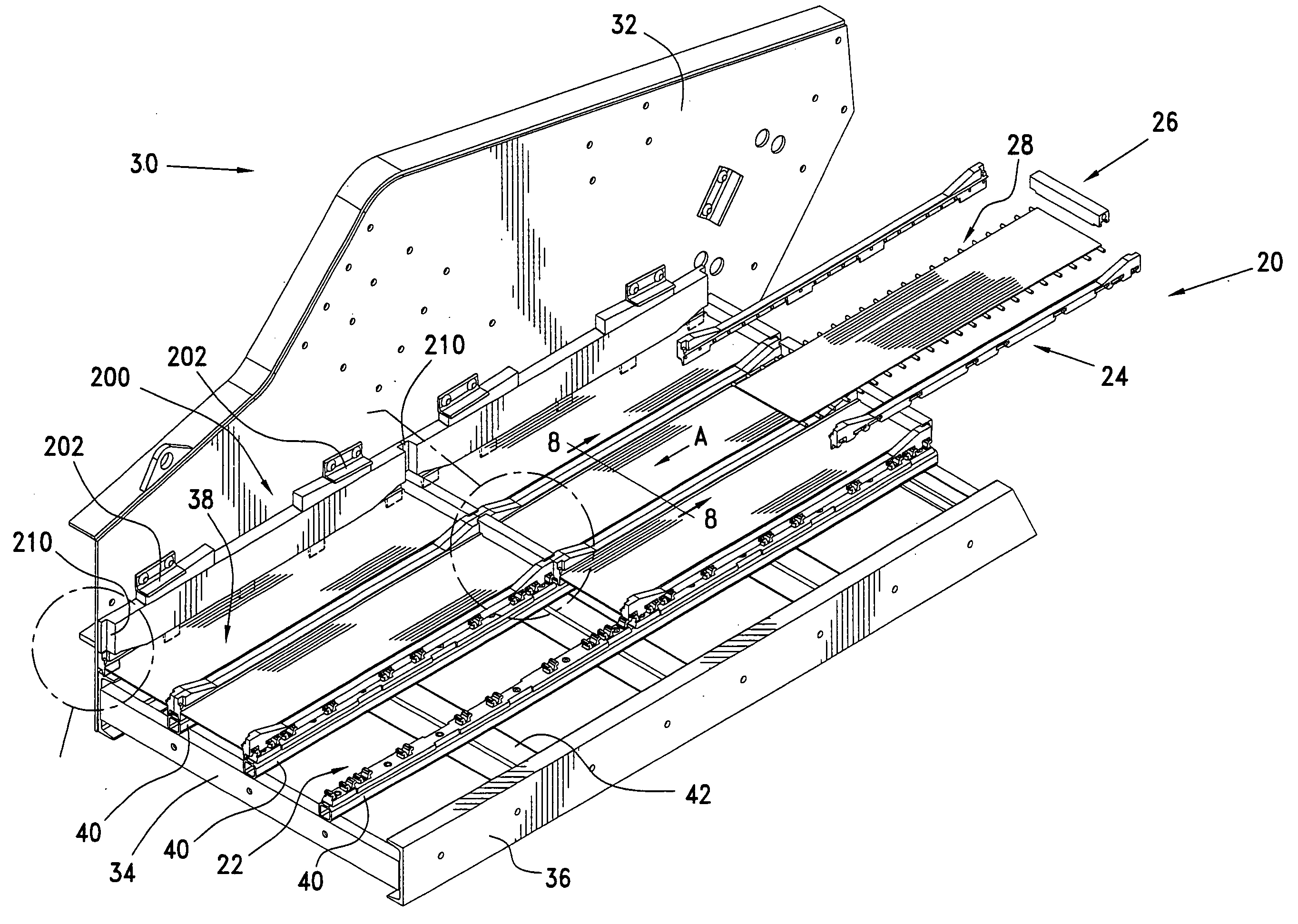
[0018] As will be discussed in detail in the description of the preferred embodiment, which is set forth subsequently, the screen panel retainer system in accordance with the present invention is usable in a vibrating separatory device to secure screen panels to existing screen stringer rails that are provided with spaced holes on their upper faces. The screen panels are retained in place by being provided with longitudinally extending screen edge strips that are configured with periodically spaced transverse pockets. These pockets are configured to releasably receive ears that extend up from elongated center and edge retainer bars. The retainer bars are molded from a resilient material, such as polyurethane and includes a central, also elongated metal spine. The spine has a plurality of longitudinally spaced apertures, with each such aperture being sized to receive a hex-headed expander bolt. The polyurethane retainer bar also is formed with a plurality of downwardly extending retainer plugs. Each such retainer plug underlies an aperture in the metal spine. Each retainer plug includes a threaded expander nut. The plugs are sized and configured to be insertable into the cooperatively spaced holes which are situated along the top face of the screen stringer rails. Once the plugs have been placed in the rail holes, suitable expander bolts are inserted through the apertures in the spine and are threaded into the expander nuts. As the expander nuts are drawn up toward the lower surface of the retainer bar underlying the spine, the polyurethane plugs, which each encase one of the expander nuts, expand radially. This radial expansion increases the diameter and circumference of each plug so that it will not pull out of the screen retainer rail hole into which it has been inserted.
[0021] The screen panel retainer system of the present invention is usable with various vibrating separatory machines while requiring no modification of the machines. The screen stringer rails on virtually all of the currently available machines have a standard hole configuration on their upper face. The downwardly extending plugs of the center and side retainer bars of the present invention are spaced and sized to fit into those stringer bar holes. There is no need for the use of additional adapters, plates, bolting mechanism or the like, as has been the case in prior devices. The plugs are so spaced and sized that they align with, and fit into the screen stringer rail holes. A vibrating separatory machine owner can thus adapt his machine to use the screen panels provided with the screen panel retainer assembly of the present invention with virtually no modification to his machine.
[0023] As was mentioned previously, the size of the screen stringer rail holes tend to enlarge over the service life of the vibrating separatory machine. This hole enlargement has, in the past required the replacement of the screen stringer rails because the prior screen panel retention systems relied on an interference fit with only very limited possibly of expansion. In contrast, the plugs of the subject screen panel retainer system are expandable radially to an increased size that will vary with the travel distance of the expander nut toward the undersurface of the retainer bar. If the diameter of the screen retainer rail holes increases, due to abrasive action of the slurry being processed, the expansion bolts of the present screen panel retainer system can be rotated to pull the expander nuts closer to the retainer bar. The effect of this is the further radial expansion of the retainer bar plugs. Such further radial expansion will compensate for screen stringer rail hole size increases. The screen panel retainer system of the present invention is thus also easily adapted for use with new machines as well as with older machines, without requiring that the screen stringer rails of these older machines be replaced.

Problems solved by technology

Such modifications or re-fittings inevitably take time, require the services of technicians and meet with resistance on the part of equipment owners who want to purchase screen panels and panel retainers that will fit the machinery they already have, without the need for any modification, revision, re-working or equipment downtime.
Over the course of time, the slurry abraids the holes and causes them to enlarge.
Since a number of the currently available panel retainer systems utilize some type of an interference fit of pins, pegs or the like into these holes, their enlargement is problematic.
At some point, the stringer bar holes become so enlarged that they will no longer engage the pins or pegs with sufficient retentive force.
In each instance, the process involves considerable work and the equipment being taken out of service.

Method used


Image

  • Screen panel retainer system
  • Screen panel retainer system
  • Screen panel retainer system

Examples


Embodiment Construction

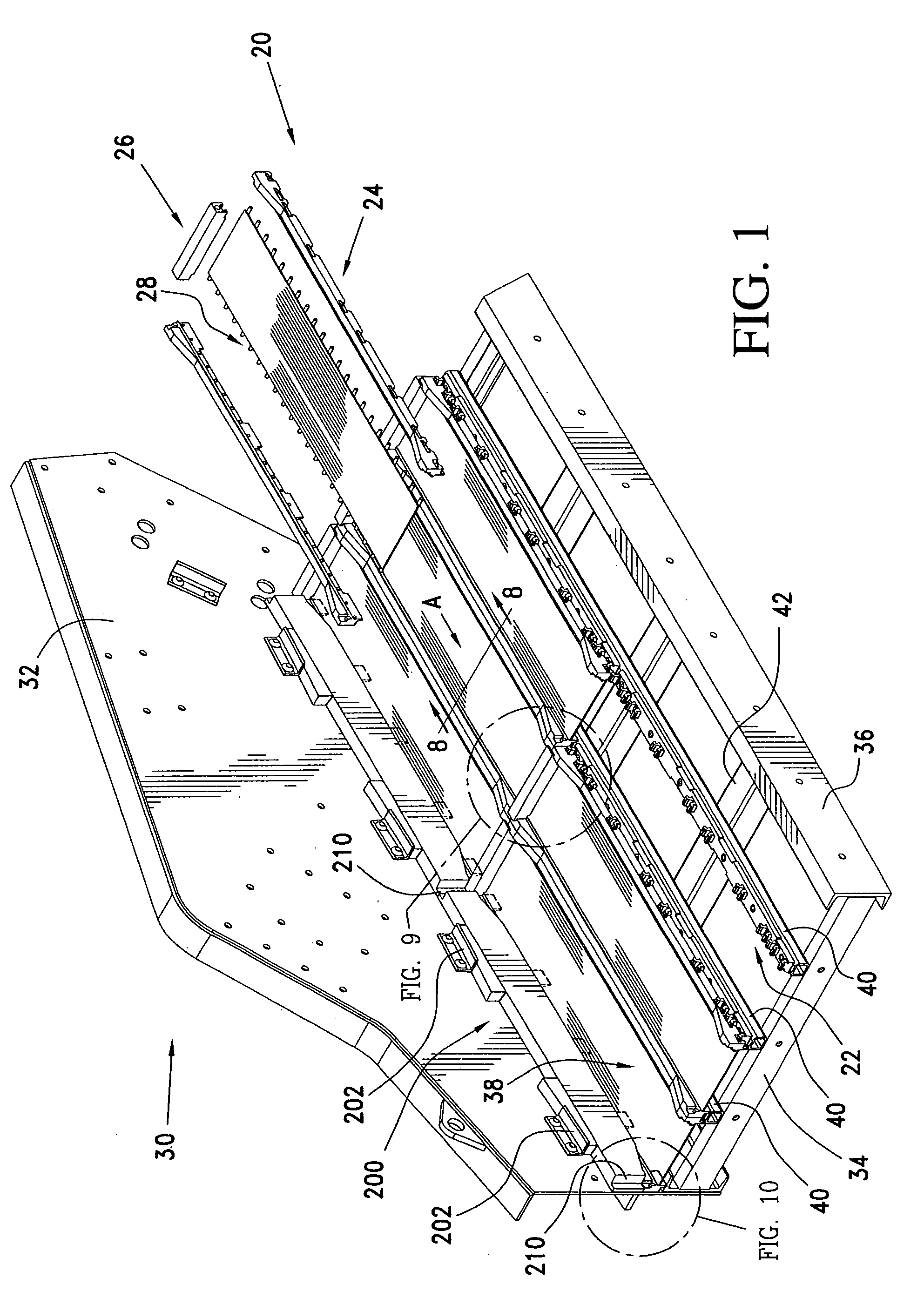
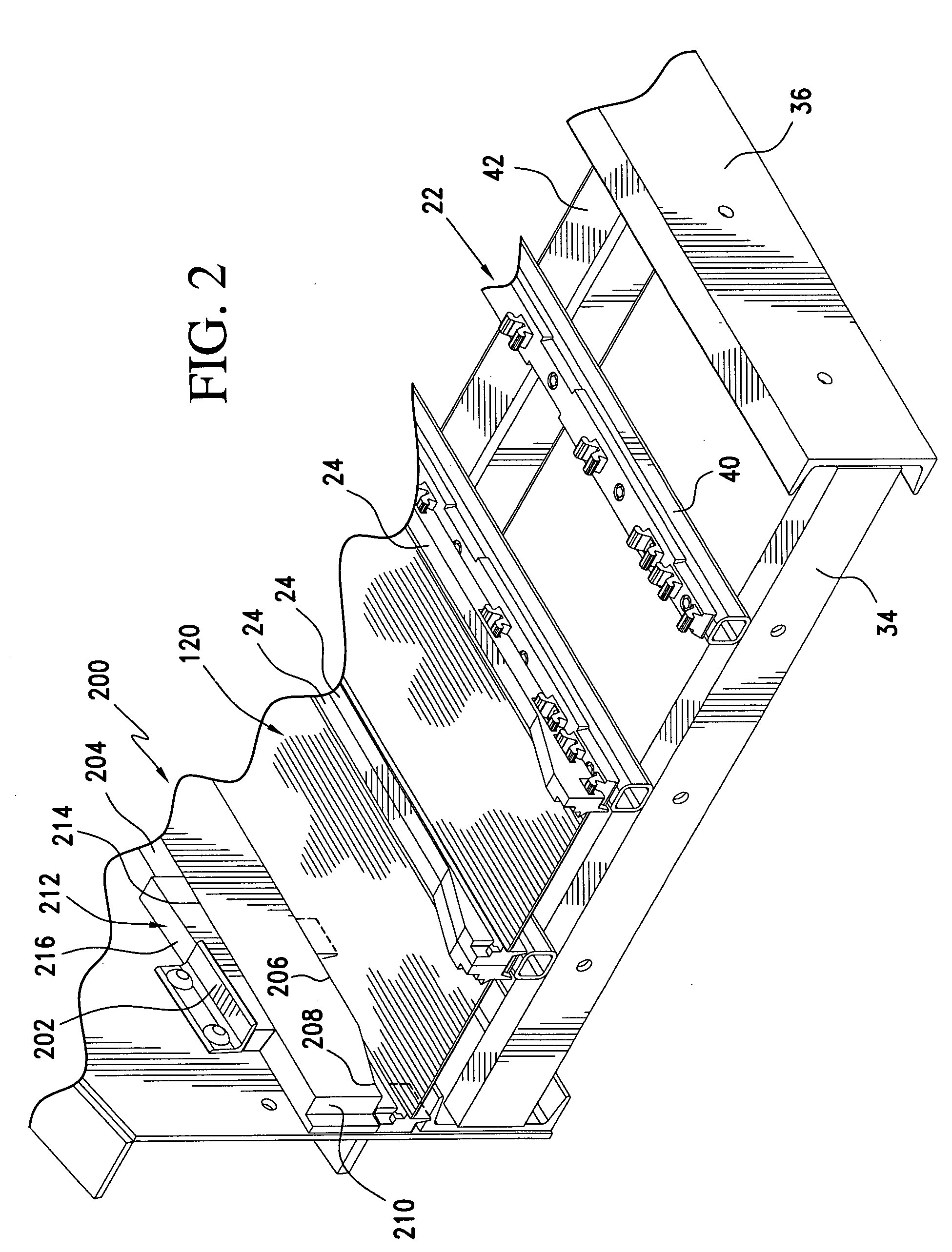
[0037] Referring initially to FIG. 1, there may be seen generally at 20 a preferred embodiment of a screen panel retainer system in accordance with the present invention. Screen panel retainer system generally at 20 includes elongated retainer bars, generally at 22, which are adapted to receive screen edge strips 24 and to also receive end dams 26. These retainer bars 22, edge strips 24 and end dams 26 form a retainer system intended to removably attach screen panels, such as screen panel 28 to a vibrating separatory machine, that is depicted somewhat schematically at 30 in FIG. 1. It will be understood that the vibrating separatory machine 30 depicted in FIG. 1 is representative of various machines of this type which are provided by a variety of manufacturers and which are used in numerous industrial applications to classify and separate particulate matter, typically in the form of a slurry of particles and water. Such vibrating separatory machines 30 typically include a pair of si...


PUM


Abstract

A screen panel retainer system is useable to retain a plurality of screen panels to a separatory machine. Retainer bars are attached to the screen stringer rails of the separatory machine by an expanding of spaced plugs that are received in holes in the stringer rails. The retainer bars each include a plurality of ears that are receivable in pockets that are situated on the inner faces of screen panel edge strips. A plurality of dams, each of which is securable to the screen edge strip ends of two adjacent screen panels, serve to further secure the screen panels in place. Screen panel removal is easily accomplished and the system is adaptable to various machine configurations.

Description

FIELD OF THE INVENTION [0001] The present invention is directed generally to a screen panel retainer system. More particularly, the present invention is directed to a screen panel retainer system for use in securing screen panels to a frame of a vibrating separatory device. Most specifically, the present invention is directed to a screen panel retainer system that utilizes elongated retainer bars, including self-expanding retainer pins and screen panel edge engaging ears, which are receivable in cooperatively shaped pockets in screen panel edge strips. The retainer pins on the elongated retainer bars are spaced to be receivable in the spaced holes or apertures which are typically situated on the upper surface of screen stringer rails provided in vibrating separatory machines. The retainer pins are expandable to securely hold the retainer bars in place and to thus retain the screen panels. The retainer bar ears releasably receive the screen panel edge strips. The screen panel retaine...

Claims


Application Information

Patent Timeline
IPC IPC(8): B07B1/00B07B1/46
CPCB07B1/46B07B2201/02B07B1/4609
Inventor BACHO, FRANK J.CONNOLLY, JAMES D.
Owner CONN WELD IND
Learn More