
Laser receiver and laser receiving system

Inactive Publication Date: 2005-08-04
FUJITSU LTD
View PDF7 Cites 2 Cited by
  • Summary
  • Abstract
  • Description
  • Claims
  • Application Information

AI Technical Summary

Benefits of technology

[0021] Also, it is another object of the present invention to provide a laser receiving system capable of detecting the acceptance position of the center point of the received laser beam on the acceptance surface without arranging numerous photo devices all over the acceptance surface.
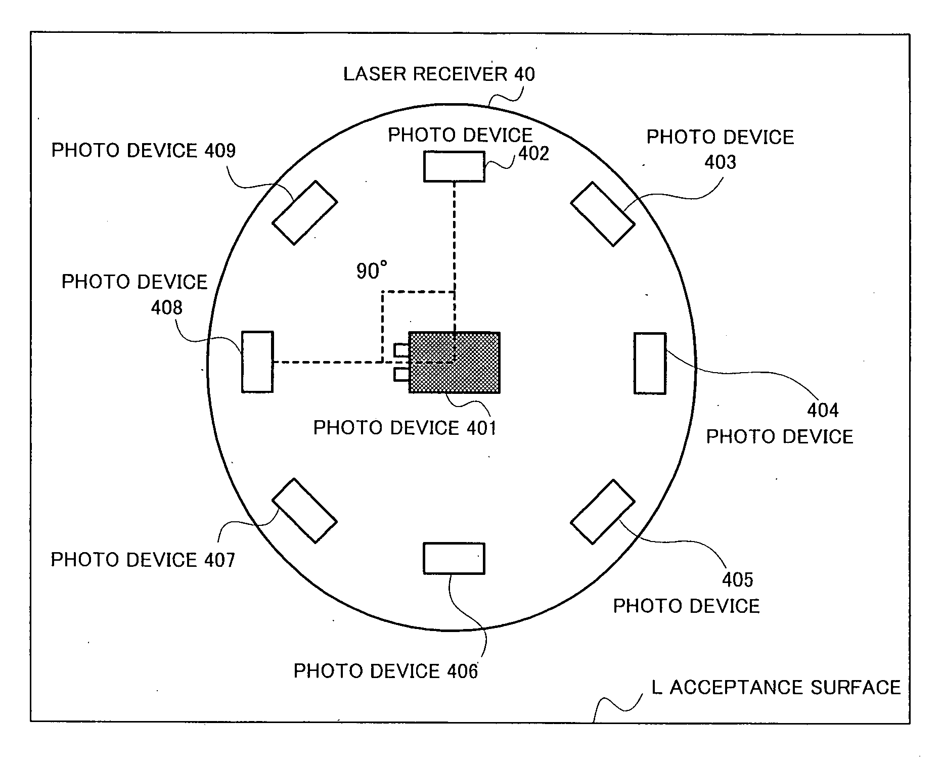
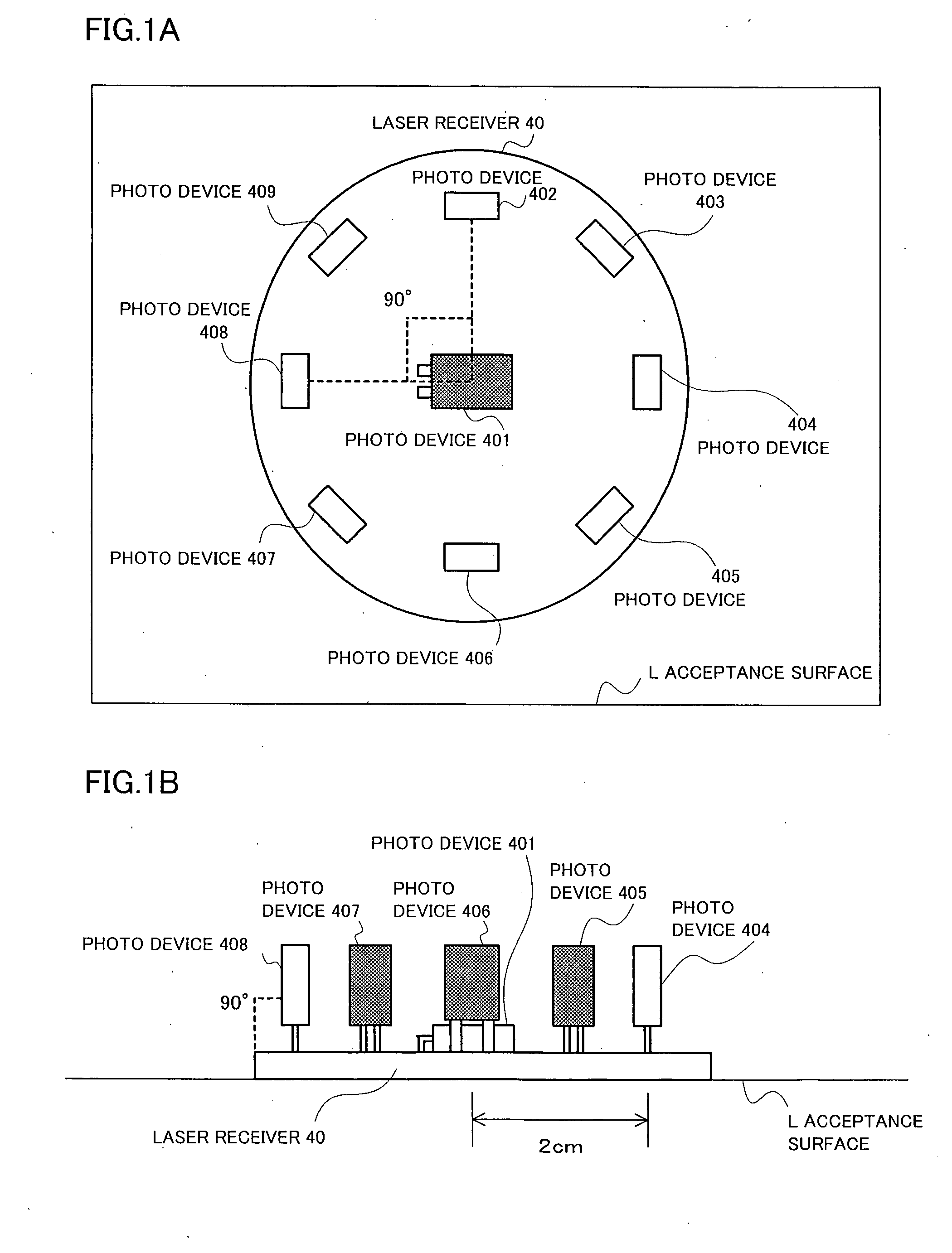
[0056] Therefore, the first and second photo devices complement each other, so to speak, with respect to mutual acceptance levels. Also, the difference of the acceptance levels between the first and the second photo devices is outstanding especially for the laser beam transmitted from the vertical direction with respect to the acceptance surface, so that the above-mentioned distance between the center point of the laser beam and the reference point and the elevation angle with respect to the reference surface can be detected at a relatively high precision.

Problems solved by technology

Therefore, it has not been possible to accept a laser beam from the horizontal direction with respect to the acceptance surface L.
However, even if the center of the laser beam hits a position off the laser receiver, it has not been able to detect how off the center of the laser beam hits the laser receiver.
Also, it has not been able to detect an acceptance angle at which the laser beam is received.
However, since it is required to arrange numerous photo devices to the entire area where the acceptance position is to be detected, a massive number of photo devices are required for the detection of the acceptance position of the laser beam within a large area.
Also, it has not been able to detect an acceptance angle at which the laser beam is received by this method.
Also in case of the laser receiver having a plurality of photo devices, it is required to arrange a massive number of photo devices in order to cover the surface of the target object, so that it is unrealistic.

Method used


Image

  • Laser receiver and laser receiving system
  • Laser receiver and laser receiving system
  • Laser receiver and laser receiving system

Examples


embodiment (

3): Embodiment of Laser Receiving System used as a Target

[0174] Hereinafter it is supposed that the laser receiving system of the present invention is used as a target or with being attached to a human body, a car and like, and a laser beam transmitted by a laser transmitter simulant of a firearm or a laser transmitter attached to a firearm is received. An example of determining whether or not the laser beam simulant of a bullet hits the target by using the determination results of the distance between center points determined by the laser receivers composing the laser receiving system will now be described.

[0175] In this embodiment, a region (area) where the target is hit is also determined when the laser beam hits the target.

[0176]FIGS. 22A and 22B show a case where a laser receiving system composed of six laser receivers of the present invention is used as a target.

[0177] As shown in FIG. 22A, the six laser receivers 40_1-40_6 are arranged at intervals of 10 cm on the target. ...


PUM


Abstract

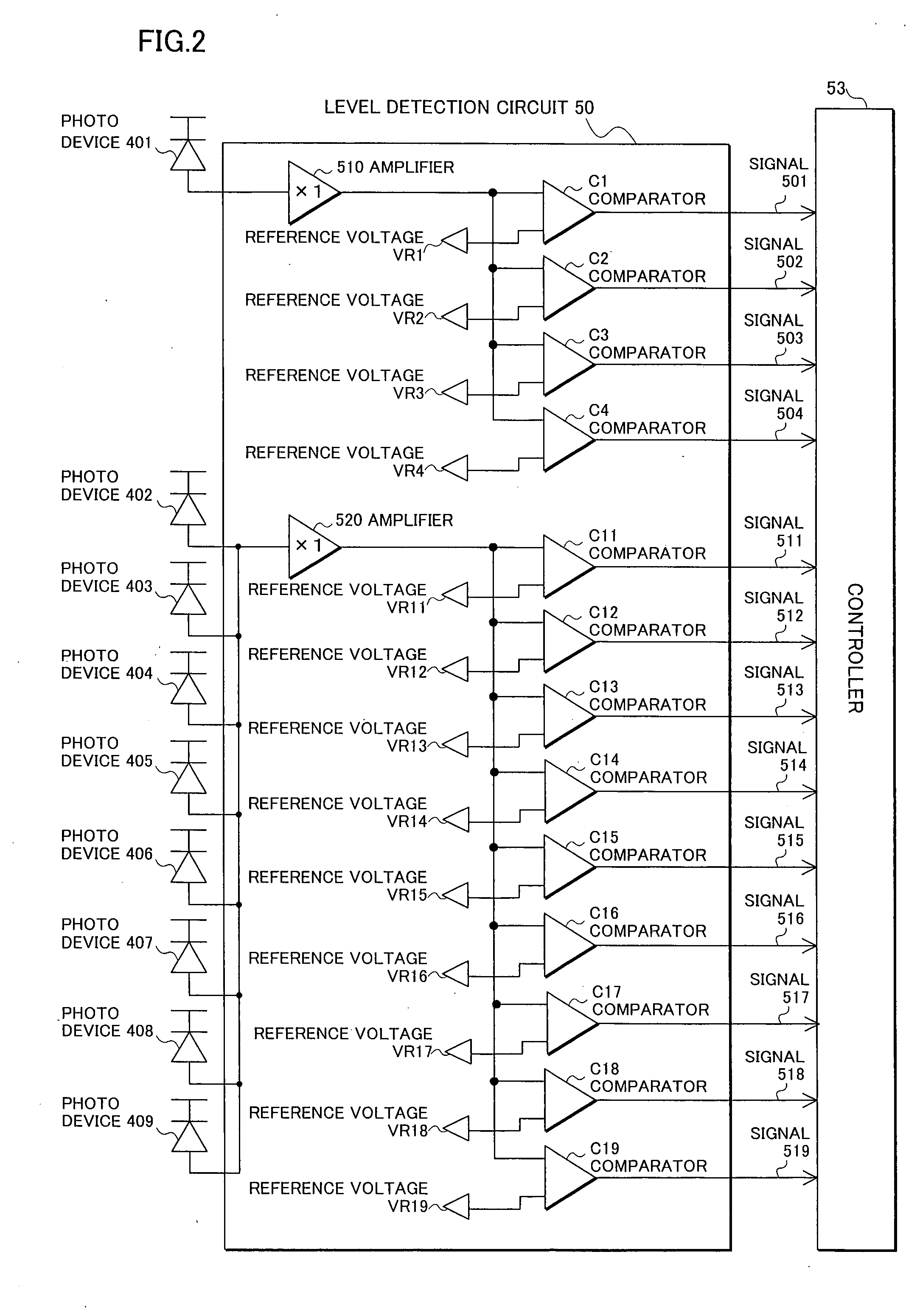
In a laser receiver receiving a laser beam from a laser transmitter and a laser receiving system composed of a plurality of laser receivers, a plurality of photo devices are arranged on an acceptance surface so that acceptance angles of the laser beam thereof are mutually different in order to detect distances between an acceptance position of a center point of a received laser beam on an acceptance surface and a reference point and an elevation angle of the received laser beam from a reference surface. Also, distance detection means respectively compare acceptance levels of the photo devices detected by the level detection means with thresholds, thereby detecting distance between the center point of the laser beam and the reference point of the acceptance surface by combination of comparison results thereof. Elevation angle detection means respectively compare acceptance levels of the photo devices detected by the level detection means with thresholds, thereby detecting elevation angles from the reference surface by combination of comparison results thereof.

Description

BACKGROUND OF THE INVENTION [0001] 1. Field of the Invention [0002] The present invention relates to a laser receiver and a laser receiving system, and in particular to a laser receiver receiving a laser beam from a laser transmitter and a laser receiving system composed of a plurality of laser receivers. [0003] 2. Description of the Related Art [0004] Some conventional laser receivers have a single photo device (photoreceptor device or receiving optics) while others have a plurality of photo devices. Any of the laser receivers has the photo devices arranged therein so that a directivity and an acceptance sensitivity suitable for the purposes of the systems may be achieved in consideration of the directivities of the photo devices. [0005]FIG. 29 shows directivity of a general photo device. When a photo device 10 is arranged on an acceptance surface L as shown in FIG. 29, the acceptance sensitivity in a vertical direction (zenithal direction) with respect to the acceptance surface L ...

Claims


Application Information

Patent Timeline
IPC IPC(8): G01C21/02G01C21/24G01J1/42G01S3/781G01S3/783G01S3/784G01S5/16G01S11/12G03G15/04
CPCG01J1/4228G01S3/781G01S11/12G01S3/784G01S5/16G01S3/783
Inventor AKANO, HIROKI
Owner FUJITSU LTD
Learn More