Brake Device For A Two-Wheeled Motor Vehicle, And Method Of Using Same

a two-wheeled motor vehicle and brake device technology, applied in the direction of brake systems, cycle brakes, cycle equipments, etc., can solve the problems that the reduction of rear-wheel load during the front-wheel side braking operation cannot be accurately detected in the device, and the reduction of rear-wheel load during the front-wheel side braking operation cannot be accurately detected, so as to prevent additional accurately determine the reduction of rear-wheel load

Active Publication Date: 2005-08-04
HONDA MOTOR CO LTD
View PDF13 Cites 21 Cited by
  • Summary
  • Abstract
  • Description
  • Claims
  • Application Information

AI Technical Summary

Benefits of technology

[0007] In braking devices employing CBS, a technology is currently being studied for determining, in an early stage, if the rear-wheel load reduces during the front wheel side braking operation, and for preventing additio

Problems solved by technology

Thus, the reduction of the rear-wheel load during a front wheel braking operation cannot be accurately detected in a device adopting a brake system in which the front and rear wheel braking devices are operated in conjunction with each other by a braking operation of one of the front and re

Method used


Image

  • Brake Device For A Two-Wheeled Motor Vehicle, And Method Of Using Same
  • Brake Device For A Two-Wheeled Motor Vehicle, And Method Of Using Same
  • Brake Device For A Two-Wheeled Motor Vehicle, And Method Of Using Same

Examples


Embodiment Construction

[0040] Next, a selected illustrative embodiment of the present invention will be described, with reference to the drawings. It should be understood that only structures considered necessary for clarifying the present invention are described herein. Other conventional structures, and those of ancillary and auxiliary components of the system, are assumed to be known and understood by those skilled in the art.

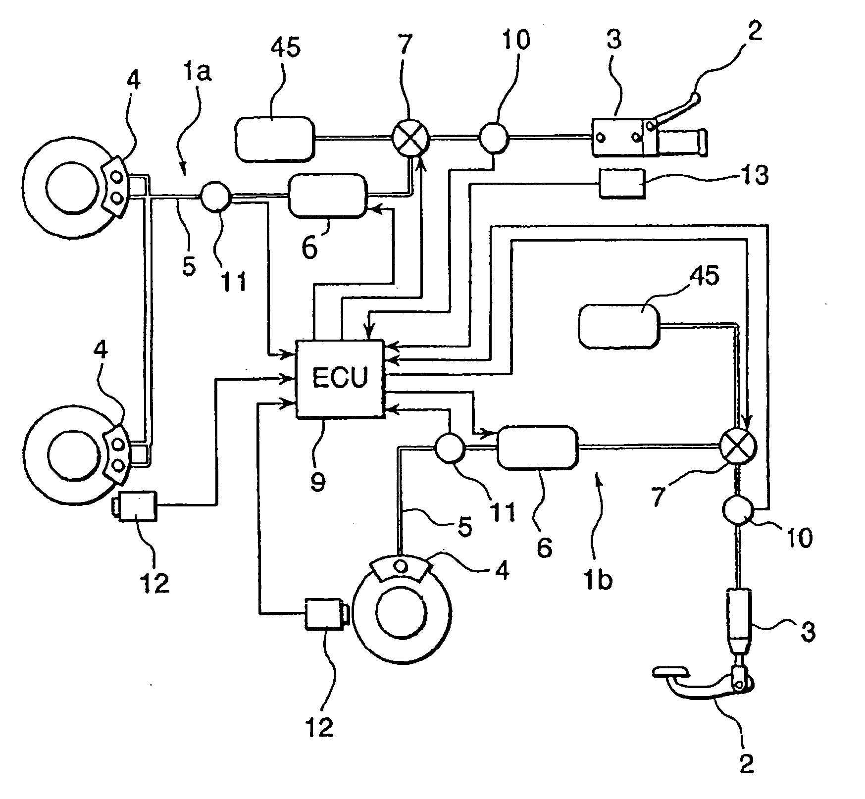
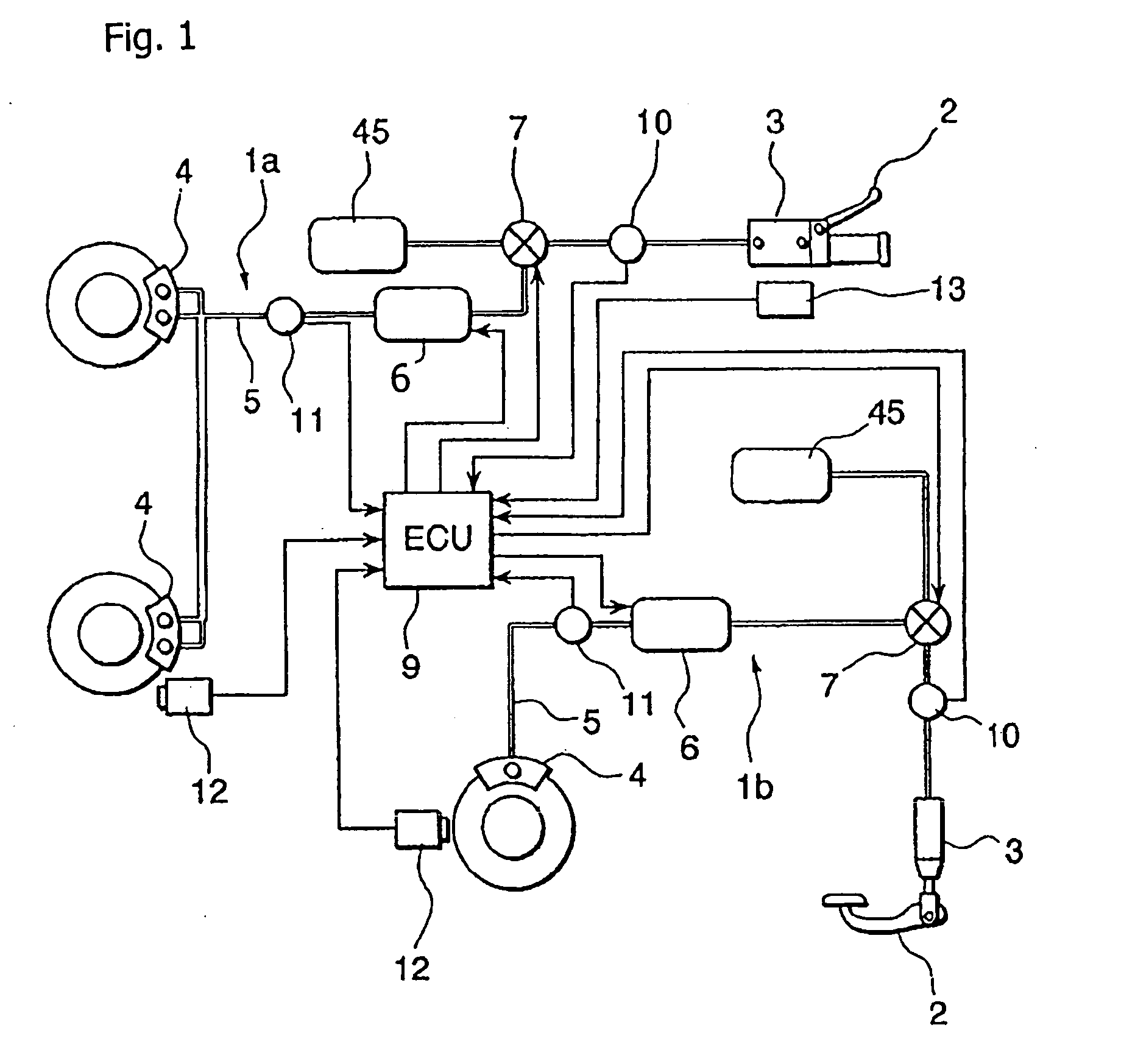
[0041]FIG. 1 is an overall schematic view of a braking device according to a selected illustrative embodiment of the present invention. As shown in FIG. 1, the braking device of this embodiment includes a front wheel brake circuit 1 at a front wheel, and a rear wheel brake circuit 1b at a rear wheel, each of the circuits being independent of each other In the respective front and rear brake circuits 1a, 1b of this embodiment, although there are some differences between the two circuits, all the other basic constituents are substantially the same. For example, brake circuits 1a an...


PUM


Abstract

In a braking device of a motorcycle, in which a rear wheel braking mechanism is operated in conjunction with a front wheel braking operation, accurate determination of a reduction in rear wheel load is provided, and additional reduction of the rear-wheel load is prevented. Determination of a reduction in rear-wheel load is based on vehicle speed in the front wheel braking operation, hydraulic pressure of a brake caliper on the front wheel side, and respective slip ratios of the front and rear wheels. When the rear-wheel load is reducing, hydraulic pressure of a brake caliper on the rear wheel side is controlled so as to keep the slip ratio of the rear wheel at or below a set value. A hydraulic modulator supplies/evacuates the hydraulic pressure to/from the brake caliper on the rear wheel side, and the slip ratio of the rear wheel is controlled by electrically controlling the hydraulic modulator.

Description

CROSS-REFERENCE TO RELATED APPLICATIONS [0001] The present invention claims priority under 35 USC 119 based on Japanese patent application No. 2004-024042, filed on Jan. 30, 2004. The subject matter of the priority document is incorporated by reference herein. BACKGROUND OF THE INVENTION [0002] The present invention relates to a braking device for a two wheeled motor vehicle such as a motorcycle. More particularly, the present invention relates to a braking device for a motorcycle which can coordinate operation of a rear wheel braking mechanism with operation of a front wheel braking mechanism. [0003] A braking device for a motorcycle, that is capable of detecting reduced rear-wheel load resulting from braking of the front wheel, and thereby preventing trouble with brake control due to the reduction of the rear-wheel load, is known. One example of such a device is disclosed in Japanese Laid-Open Patent No. 2002-29403. [0004] The braking device described in Japanese Laid-Open Patent ...

Claims


Application Information

Patent Timeline
IPC IPC(8): B60T8/1766B60T8/26B60T8/32B60T8/66B60T13/16B62L3/08
CPCB60T8/261B60T13/165B60T8/3225
Inventor TANI, KAZUHIKONAKAYAMA, MASANOBUNISHIMOTO, YUKIMASA
Owner HONDA MOTOR CO LTD
Why Eureka
Try Eureka