
Displaying a wide field of view video image

a wide field of view and video image technology, applied in the field of wide field imaging, can solve problems such as the inability to produce video panoramas

Inactive Publication Date: 2005-08-04
HEWLETT PACKARD DEV CO LP
View PDF10 Cites 88 Cited by
  • Summary
  • Abstract
  • Description
  • Claims
  • Application Information

AI Technical Summary

Benefits of technology

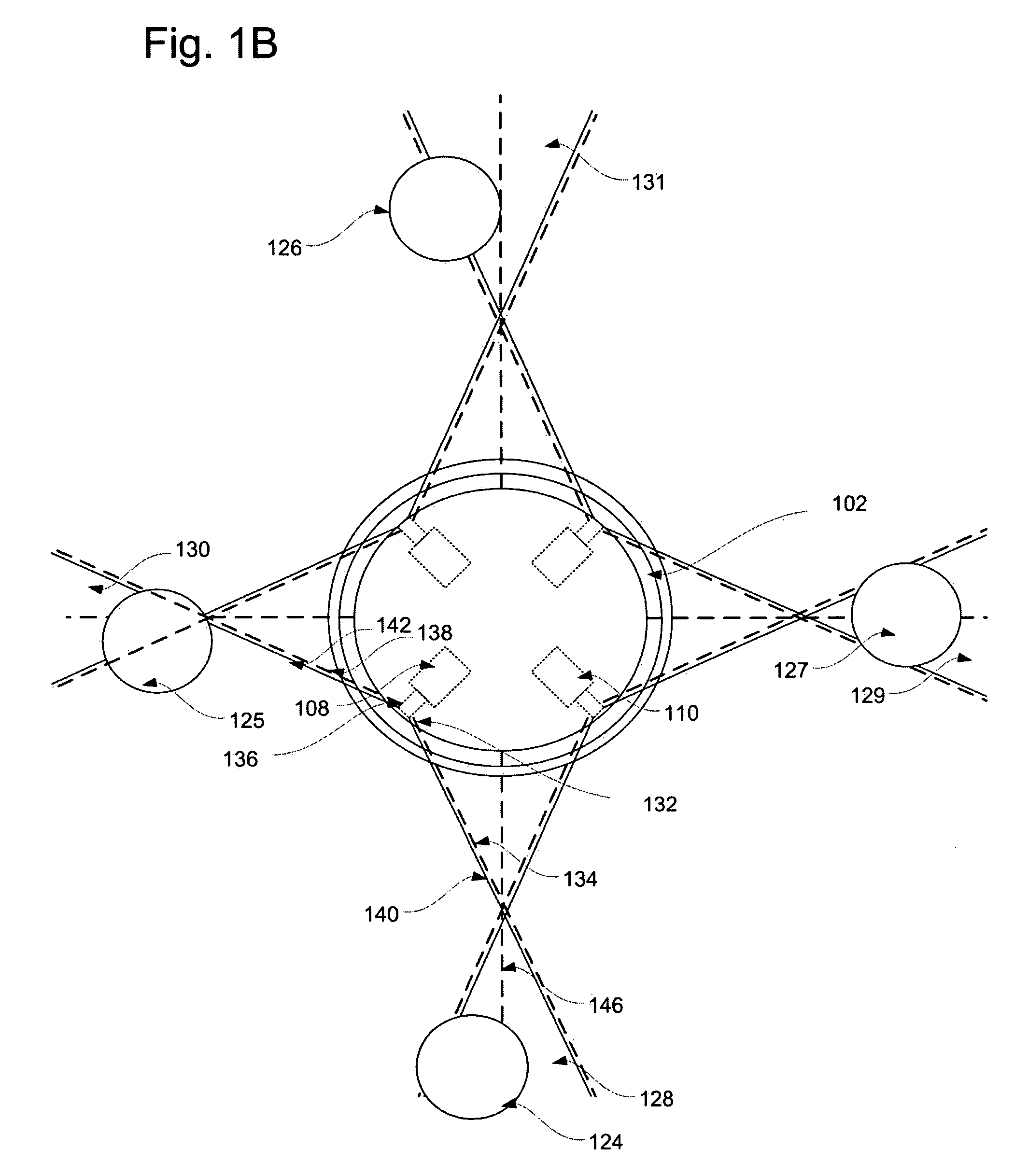
[0006] In one aspect of the present invention provides a system for displaying a wide field of view video image of a location. The system comprises a plurality of location cameras for placement at the location. The location cameras capture the wide field of view video image as a plurality of individual video images that together cover the desired field of view. The system also comprises a distance sensor unit. The distance sensor unit senses distances of closest objects in one or more overlap areas between field of views of the neighboring location cameras. The system further comprises a display unit for displaying the plurality of individual video images to a user for creating a visual experience of the location based on the sensed distances to the closest object.

Problems solved by technology

However, such techniques are based on panoramic still images, and cannot produce video panoramas since the product of exposure time and the number of images that must be taken exceeds the time per frame of a typical video sequence.

Method used


Image

  • Displaying a wide field of view video image
  • Displaying a wide field of view video image
  • Displaying a wide field of view video image

Examples


Embodiment Construction

[0015] The system of the example embodiment consists of two main parts, a display system at the user's location and a remotely located surrogate device.

[0016] The surrogate device is connected to the display system via high-speed networking in the example embodiment, and stands in the place of the user at the remote location.

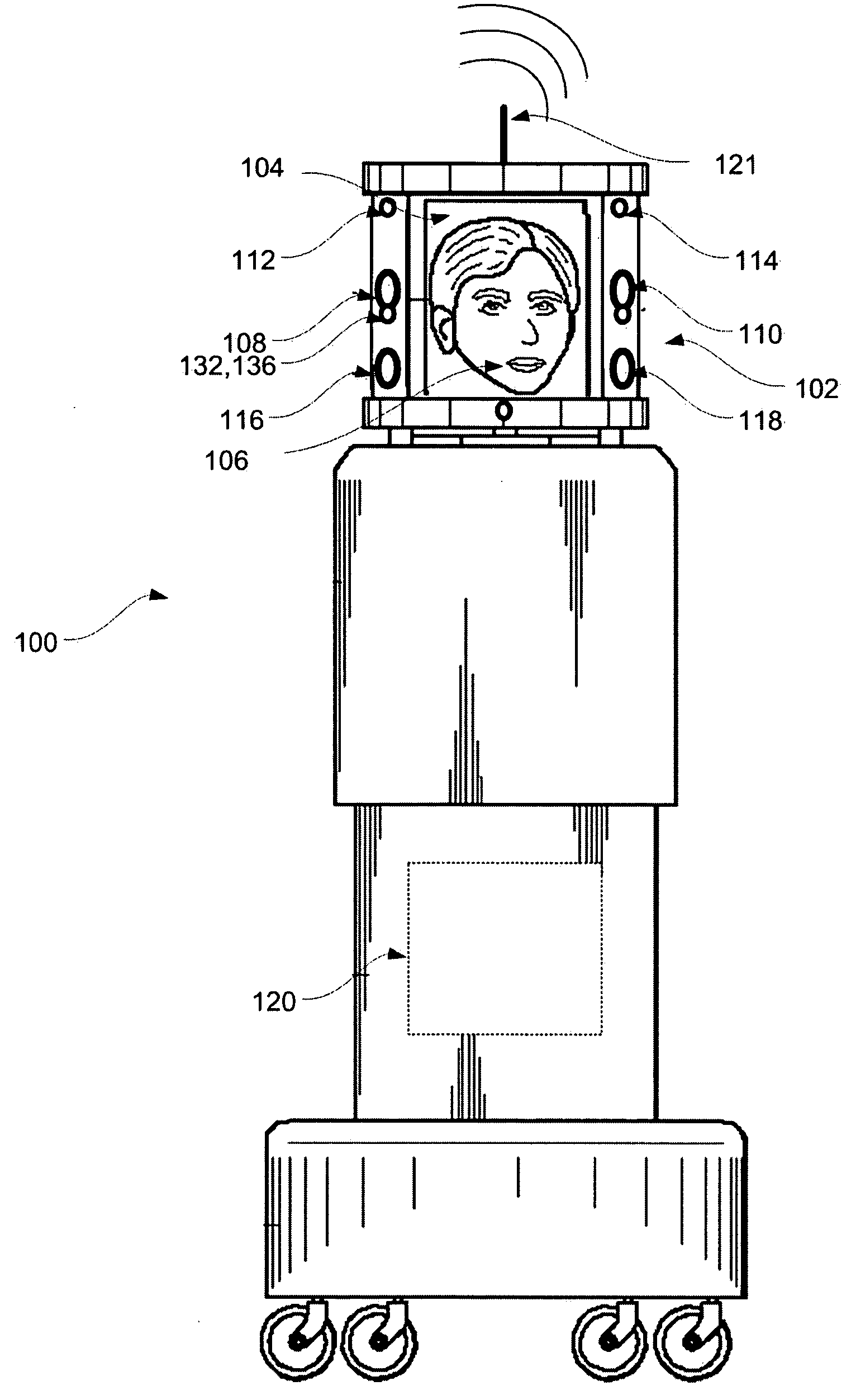
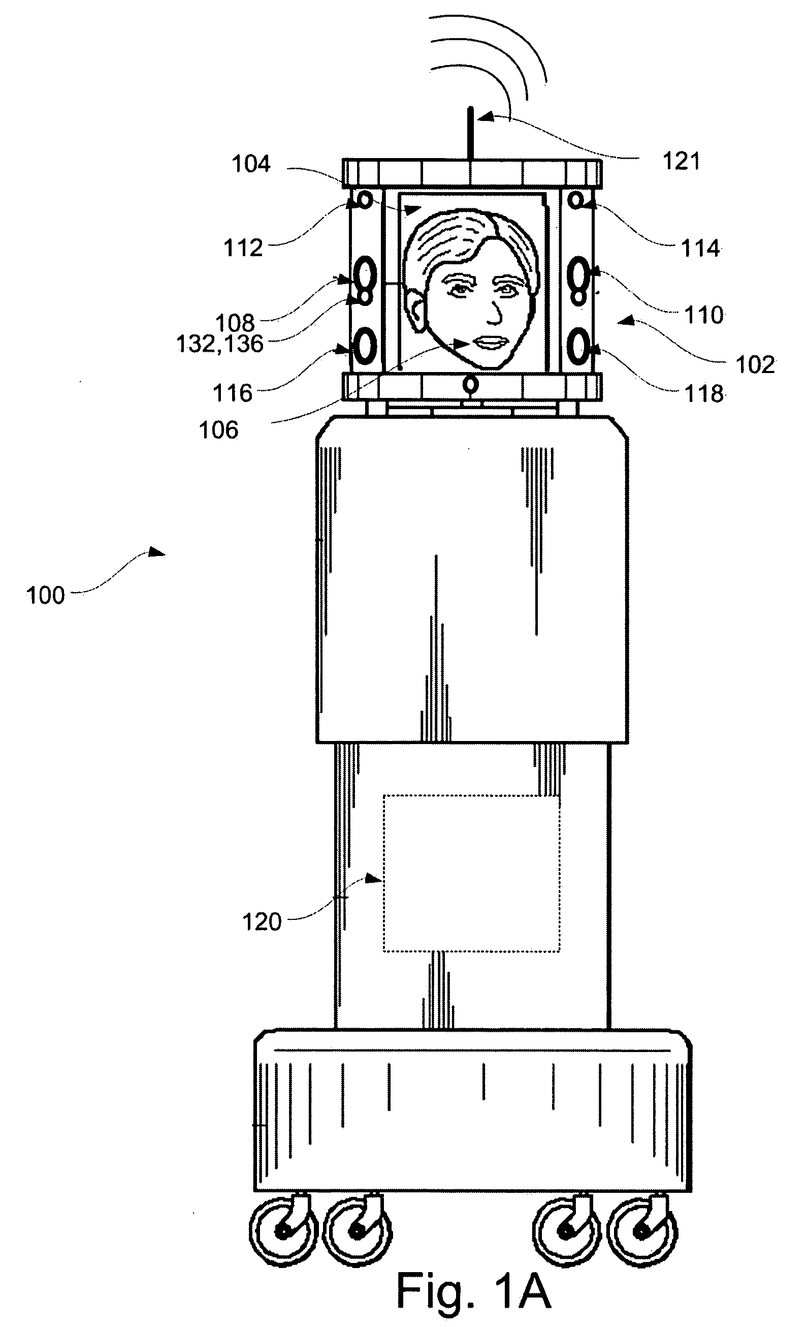
[0017]FIG. 1A shows a schematic drawing of the surrogate device 100 of the example embodiment. The surrogate device 100 has a “head”102 made from four display panels, e.g. 104 in a square, outwardly facing arrangement. Live video of the user's face 106 is displayed on all four sides, namely on all four LCD panels of the surrogate device 100.

[0018] Four cameras e.g. 108, 110 in the corners of the surrogate devices head 102 together capture 360° surround live video from the remote location at which the surrogate device 100 is located. The cameras e.g. 108, 110 are positioned near the mid-point of the height of the displays e.g. 104 in the example embodiment, to...


PUM


Abstract

A system for displaying a wide field of view video image of a location. A series of location cameras disposed at the location captures the wide filed of view video image as a series of individual video images covering the desired field of view. A distance sensor unit senses distances of closest objects in one or more overlap areas between field of views of the location cameras from the two or more location cameras covering each respective overlap area. A display unit displays the series of individual video images to a user for creating a visual experience of the location. A processor unit determines a horizontal span of each individual video image displayed by the display unit based on the sensed distances of the closest objects.

Description

FIELD OF THE PRESENT INVENTION [0001] The present invention relates to wide field imaging. BACKGROUND OF THE PRESENT INVENTION [0002] Systems that seek to acquire very wide field of view (e.g. 360°) images are significant for a number of applications in both still and motion picture capturing and display. One such system employs a camera rotating around the horizontal of its focal plane used for capturing still panoramic photographs. Many images are taken, ranging from of the order of about 7 for consumer photographs to more than 100 for professional panoramas. The camera is typically mounted on a tripod, with the pan axis centered on the horizontal center of the focal plane. Parallax errors are reduced as the number of images is increased. [0003] Sophisticated software has been recently developed that allows a consumer-quality panorama to be built from a series of handheld images. However, such techniques are based on panoramic still images, and cannot produce video panoramas since...

Claims


Application Information

Patent Timeline
IPC IPC(8): H04N5/225H04N7/00
CPCH04N5/23238H04N5/2259H04N23/58H04N23/698
Inventor JOUPPI, NORM
Owner HEWLETT PACKARD DEV CO LP
Learn More