Liquid crystal projector, liquid crystal device and substrate for liquid crystal device

a liquid crystal projector and liquid crystal technology, applied in the field of liquid crystal projectors, can solve the problems of inability to narrow viewing angle of the liquid crystal device, and disadvantages of projectors being smaller, so as to achieve the effect of high image contrast ratio and increase the contrast ratio of the projected imag

Active Publication Date: 2005-08-04
FUJIFILM CORP
View PDF8 Cites 39 Cited by
  • Summary
  • Abstract
  • Description
  • Claims
  • Application Information

AI Technical Summary

Benefits of technology

[0021] The form birefringence layer may be formed in the liquid crystal device. In this case, the liquid crystal device has a liquid crystal layer between a pair of substrate bodies. The form birefringence layer, formed on at least one of the inner and outer surfaces of the substrate body, compensates retardation caused by birefringence in the liquid crystal layer.
[0023] According to the present invention, since the inorganic form birefringence layer is used as the retardation compensator to increase the contrast ratio of the image projected on the screen, it is possible to utilize the projector with high image contrast ratio for long-term use, such as a household television.

Problems solved by technology

The liquid crystal device has the disadvantage of narrow viewing angle because of its birefringence.
Then, it is impossible to increase the contrast ratio of the projected image even if the observer tries to change the viewing angle.
Such projection lens system, however, is disadvantageous in terms of making the projector smaller.
Higher intensity of the light source causes excessive heat to the retardation compensator.
Because of its low durability, it is difficult to utilize the organic retardation compensator to the home use liquid crystal projection TV.
The retardation compensator made of sapphire or crystal has great durability for long-term use, but the sapphire and crystal are expensive.
Accordingly, sapphire or crystal retardation compensator is not appropriate for household type liquid crystal projector in terms of manufacture cost, regardless of great durability.
Since the micro lens array changes the incidence angle of incident light to the liquid crystal device, it is difficult to obtain the designed effect of the retardation compensator.
Moreover, the micro lens array limits the position of the retardation compensator.

Method used


Image

  • Liquid crystal projector, liquid crystal device and substrate for liquid crystal device
  • Liquid crystal projector, liquid crystal device and substrate for liquid crystal device
  • Liquid crystal projector, liquid crystal device and substrate for liquid crystal device

Examples


Embodiment Construction

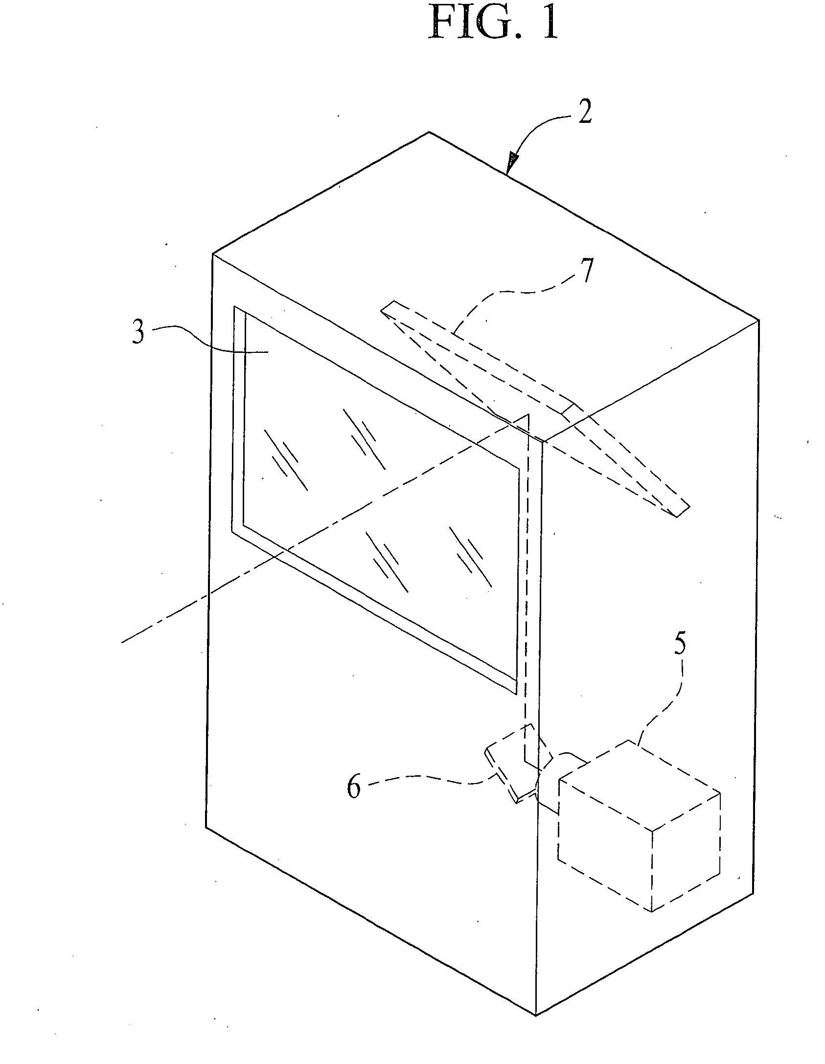
[0042] A liquid crystal projector of rear projection type is depicted in FIG. 1. A diffuse transmissive screen 3 is provided in the front side of a housing 2 of the liquid crystal projector. An image projected from the rear side of the screen 3 is observed from the front side thereof. The image projected by an image projection unit 5 with a liquid crystal device, assembled in the housing 2, is reflected on the mirror 6, 7 and focused on the rear side of the screen 3. The liquid crystal projector may be used as a wide screen television by incorporating well-known electrical circuits such as a tuner circuit, a video / sound signal reproduction circuit. In that case, the reproduced video images are displayed on the liquid crystal device of the image projection unit.

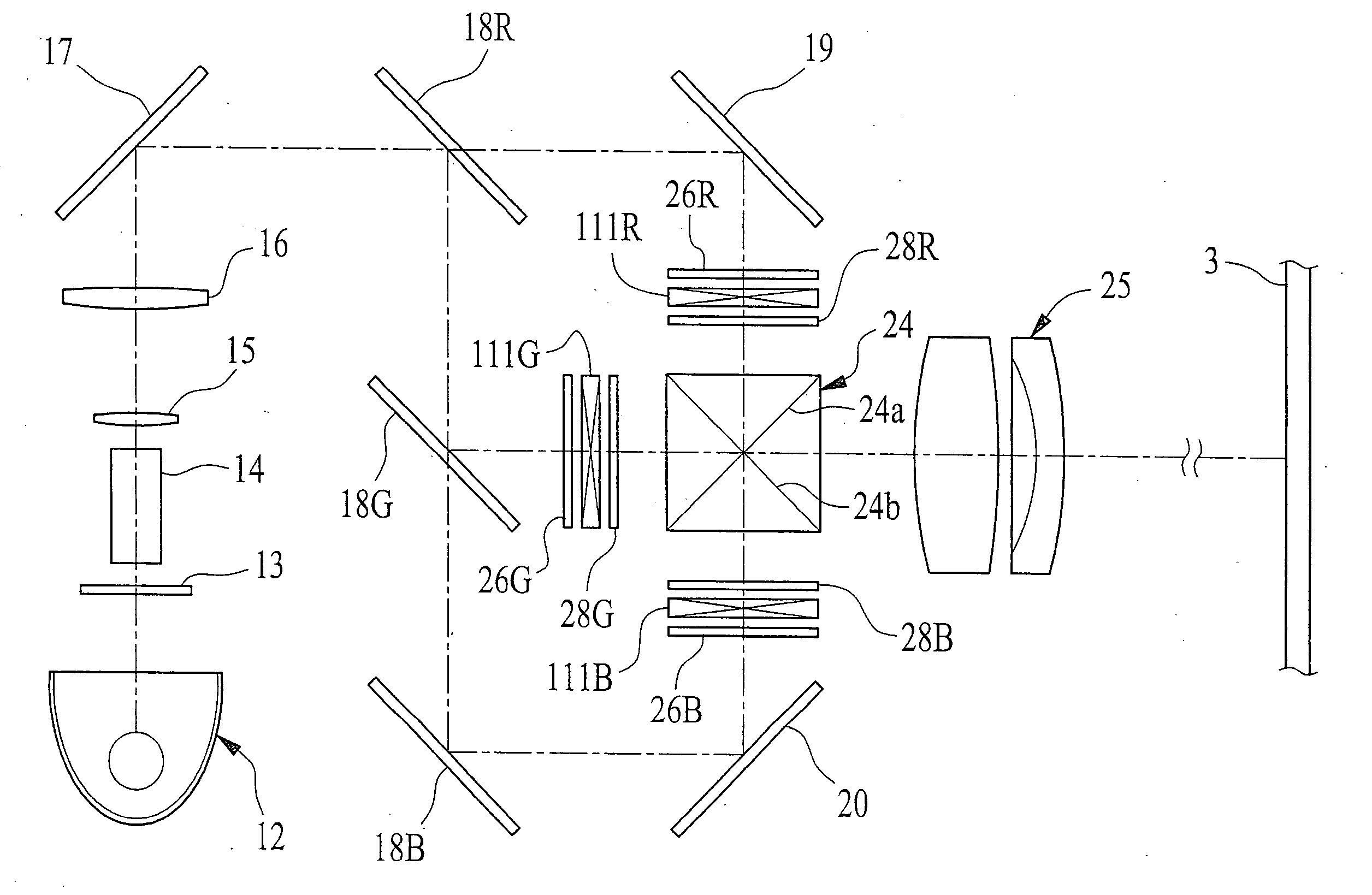
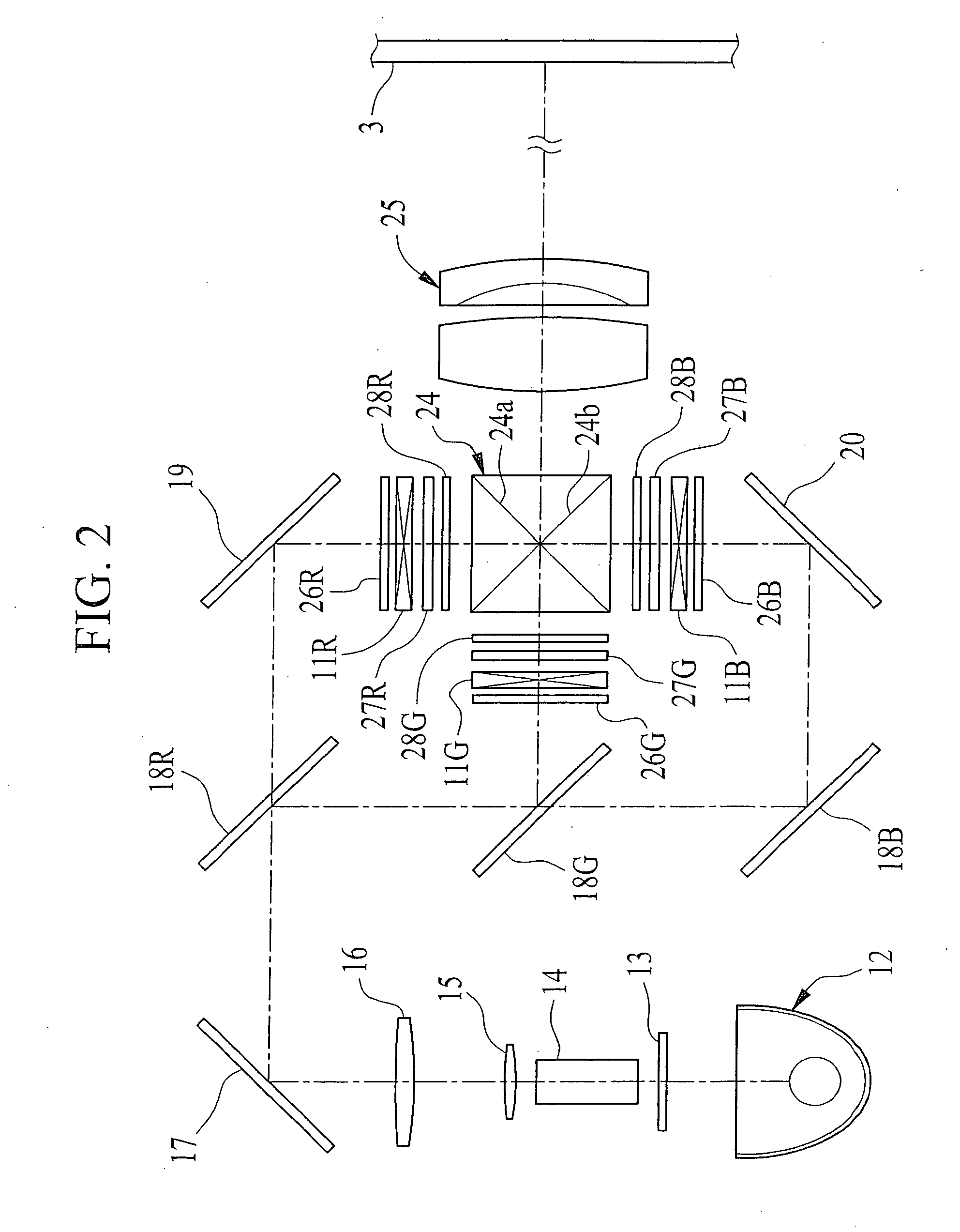
[0043] As shown in FIG. 2, the image projection unit 5 has three transmissive liquid crystal devices for red, green and blue images 11R, 11G, 11B to project a full color image onto the screen 3. Emission light from a light so...


PUM

PropertyMeasurementUnit
thicknessaaaaaaaaaa
refractive indicesaaaaaaaaaa

Abstract

Red incident light is reflected on a mirror (19) and linearly polarized by a polarizer (26R). Linearly polarized incident light enters a transmissive liquid crystal device (11R), in which oblique incident light is changed into elliptically polarized light. A retardation compensator (27R) between the liquid crystal device (11R) and an analyzer (28R) has an inorganic form birefringence layer. The retardation compensator (27R) yields birefringence effect to change elliptical polarized light into linearly polarized light. Linearly polarized light from the retardation compensator (27R) can pass the analyzer (28R) without decreasing intensity, and enters a color recombining prism (24). The liquid crystal device (11R) may have the inorganic form birefringence layer. Retardation in green and blue light is also compensated in the same manner. Red, green and blue image light, mixed in the color recombining prism (24), is projected onto a screen 3 by a projection lens system (25).

Description

TECHNICAL FIELD [0001] The present invention relates to liquid crystal projector to display an image on a liquid crystal device and to project the image onto a screen. BACKGROUND ART [0002] A liquid crystal projector is widely used to project an image onto a screen. The liquid crystal projector illuminates the image displayed on a transmissive or reflective liquid crystal device, and focuses the image on the screen through a projection lens system, so that many people can view the image at the same time. The liquid crystal projector has a front projection type and a rear projection type. The front projection type projector projects the image from the front side (viewer side) of the screen, while the rear projection type projector projects the image from the rear side of the screen. [0003] Although various types of liquid crystal devices are available for the liquid crystal projector, TN (Twisted Nematic) type liquid crystal device is mainly used. The TN type liquid crystal device ha...

Claims


Application Information

Patent Timeline
Patent Type & Authority Applications(United States)
IPC IPC(8): G02F1/13363H04N9/31
CPCG02F1/13363G02F2001/133565G02F2413/02G02F2413/10H04N9/3197G02F2413/14H04N9/3105H04N9/3167G02F2413/11G02F1/133634G02F1/133565G02F1/13
Inventor NAKAGAWA, KENICHI
Owner FUJIFILM CORP
Why Eureka
Try Eureka