Methods for implement microscopy and microscopic measurement as well as microscope and apparatus for implementing them

a technology of applied in the field of methods for implementing microscopy and microscopic measurement as well as microscopes and apparatuses for implementing them, can solve the problems of difficult use of contrast microscope and differential interference microscope for observation at magnifications lower than 4, pupil aberration between illumination optical system and image-formation optical system becomes too large to keep pupils in conjugate relations, etc., to achieve easy separation

Inactive Publication Date: 2005-08-04
OLYMPUS CORP
View PDF9 Cites 69 Cited by
  • Summary
  • Abstract
  • Description
  • Claims
  • Application Information

AI Technical Summary

Benefits of technology

[0032] While the wavefront introduced in the pupil position of the image-formation optical system is substantially symmetrically changed, two images with inverted contrasts are taken of the same object under observation, and a subtract operation is applied between the two images thereby providing an enhanced contrast.
[0052] With the method and apparatus for implementing microscopic measurements as recited above, it is possible to form an image subjected to the subtract operation thereby obtaining image information of growing cells, which are less affected by external perturbations such as illumination variations. In particular, a portion with no cells distributed is little affected by external perturbations.
[0053] By carrying out the extraction of a cell-free portion at first, it is possible to make an easy separation between a cell-containing portion and the cell-free portion.

Problems solved by technology

Like living cells, minute pits and projections occurring on semiconductor substrates or metal surfaces, too, are observed under differential interference microscopes, because of being incapable of bright-field observations.
However, as the magnification of a viewing optical system goes down to make a viewing range wider, pupil aberration between the illumination optical system and the image-formation optical system becomes too large to keep the pupils in conjugate relations.
This renders it difficult to use both the phase contrast microscope and the differential interference microscope for observations at magnifications lower than 4.
However, both the phase contrast microscope and the differential interference microscope offer a problem in this regard.
Further, with living cells under observation by the phase contrast microscope, the coexistence of an intensity component that is not proportional to the phase difference of living cells and called a halo renders observations difficult.
Furthermore, the coexistence of external perturbations such as illumination variations renders observations much harder.
With visual observations and measurements of growing cells in a culture vessel, there are problems such as longer time taken for measurements all over the culture vessel, differences from person to person, and lower repeatability.

Method used


Image

  • Methods for implement microscopy and microscopic measurement as well as microscope and apparatus for implementing them
  • Methods for implement microscopy and microscopic measurement as well as microscope and apparatus for implementing them
  • Methods for implement microscopy and microscopic measurement as well as microscope and apparatus for implementing them

Examples


Embodiment Construction

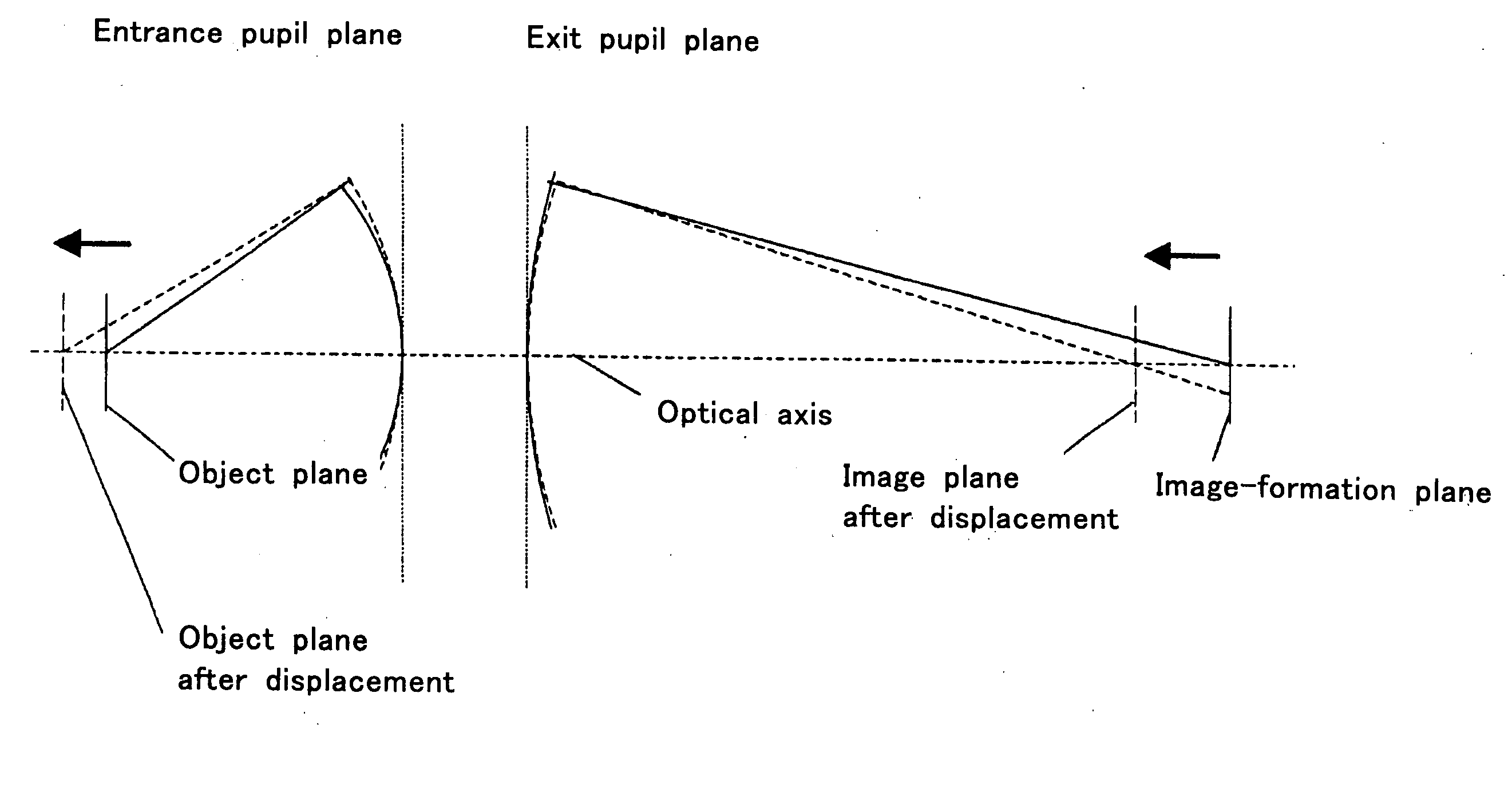
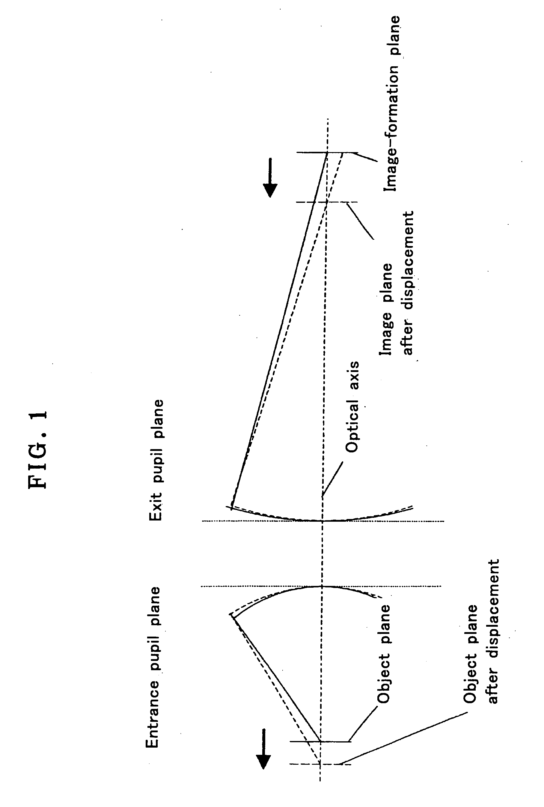
[0070] First of all, the principles of creating image contrasts proportional to the pit-and-projection phase distribution of a phase object or pits and projections on a substrate surface according to the invention are explained.

[0071]FIG. 1 is illustrative of the principles of the invention, and provides a schematic illustration of an arrangement comprising an object point and the entrance pupil, exit pupil and image-formation plane of an image-formation optical system. As an object under observation is located at a focus position as shown in FIG. 1, light coming out of an object point under observation spreads out in spherical waveform, entering the entrance pupil of the image-formation optical system, whence the incident light takes a spherical waveform of converging light, leaving the exit pupil of the image-formation optical system and converging on the image-formation plane to form an image thereon. The formed image is free from any blurring, because there is no optical path (...


PUM


Abstract

The invention relates to a microscope that enables a phase object or surface pits and projections to be observed at a relatively low image-formation magnification of 4 or lower over a wide viewing range yet in a relatively narrow spatial frequency distribution range. The microscope comprises a light source 2, an illumination optical system 3 for guiding light from the light source 2 to an object 4 under observation, a partial aperture located substantially at the pupil position 28 of the illumination optical system 3 and an image-formation optical system 15, 16, 18 for forming on the image-formation plane 19 an image 4 of the object under observation illuminated by light passing through the partial aperture, and further comprises an eyepiece optical system 6 or an image pickup optical system for viewing the image formed on the image-formation plane 19. The diameter of the image of said partial aperture at the pupil position 30 of the image-formation optical system is set smaller than the pupil diameter of the image-formation optical system, and at the pupil position 30 of the image-formation optical system there is located wavefront introduction means for introducing in the pupil position 30 of the image-formation optical system a wavefront varying in size with the pupil diameter.

Description

[0001] This application claims benefit of Japanese Application No. 2003-414158 filed in Japan on Dec. 12, 2003 and No. 2004-30431 filed in Japan on Feb. 6, 2004, the contents of which are incorporated by this reference. BACKGROUND OF THE INVENTION [0002] The present invention relates generally to methods for implementing microscopy and microscopic measurements as well as a microscope and apparatus for implementing them. More particularly, the present invention relates to a method and microscope for observing phase objects such as living cells and minute pits and projections on semiconductor substrates, metal surfaces and glass substrates and a method and apparatus for measuring the number, morphology, distribution and so on of cells cultured in a culture vessel. [0003] Living cells, being colorless and transparent, cannot be viewed through ordinary bright-field observations and, hence, are viewed by means of phase contrast microscopes or differential interference microscopes. [0004]...

Claims


Application Information

Patent Timeline
Patent Type & Authority Applications(United States)
IPC IPC(8): G02B21/00G02B21/14G02B21/36
CPCG02B21/361G02B21/14
Inventor ISHIWATA, HIROSHI
Owner OLYMPUS CORP
Why Eureka
Try Eureka