
Fire shielding battery case

Inactive Publication Date: 2005-08-04
ENERDEL
View PDF8 Cites 105 Cited by
  • Summary
  • Abstract
  • Description
  • Claims
  • Application Information

AI Technical Summary

Benefits of technology

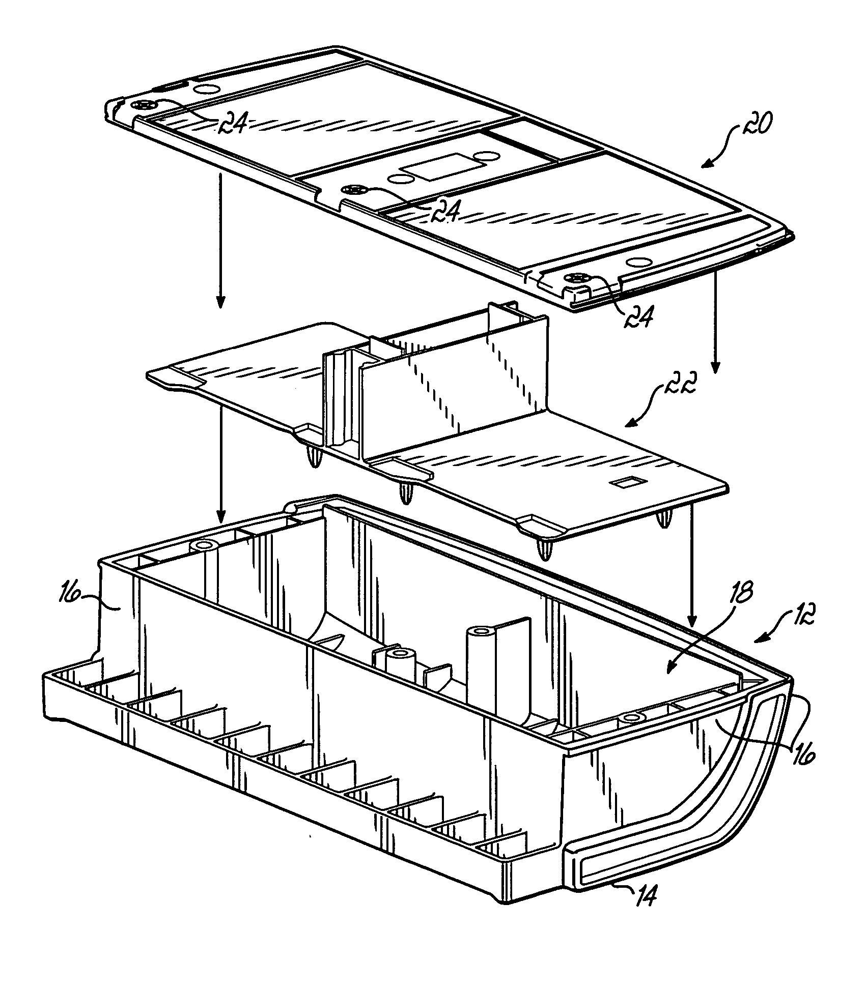
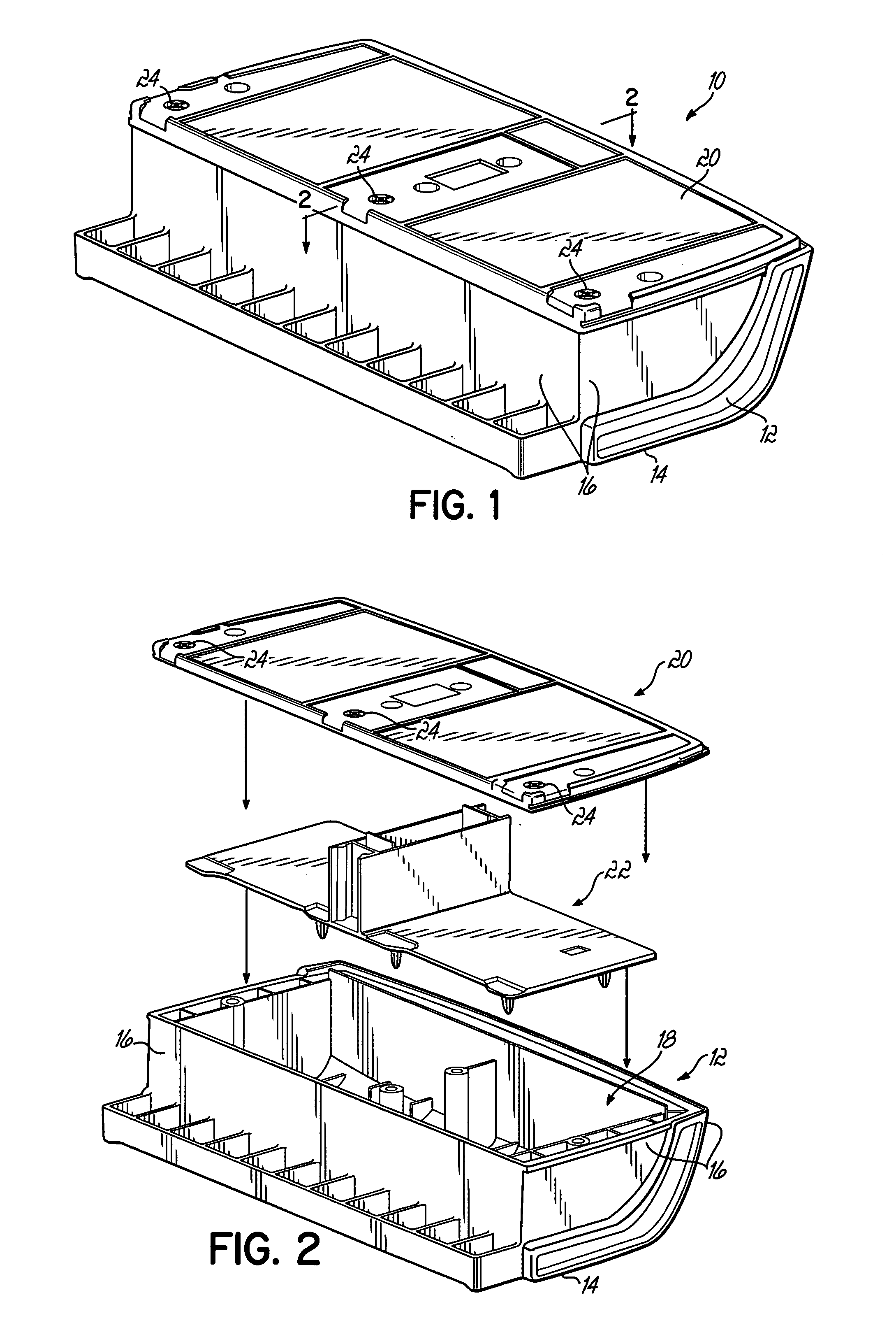
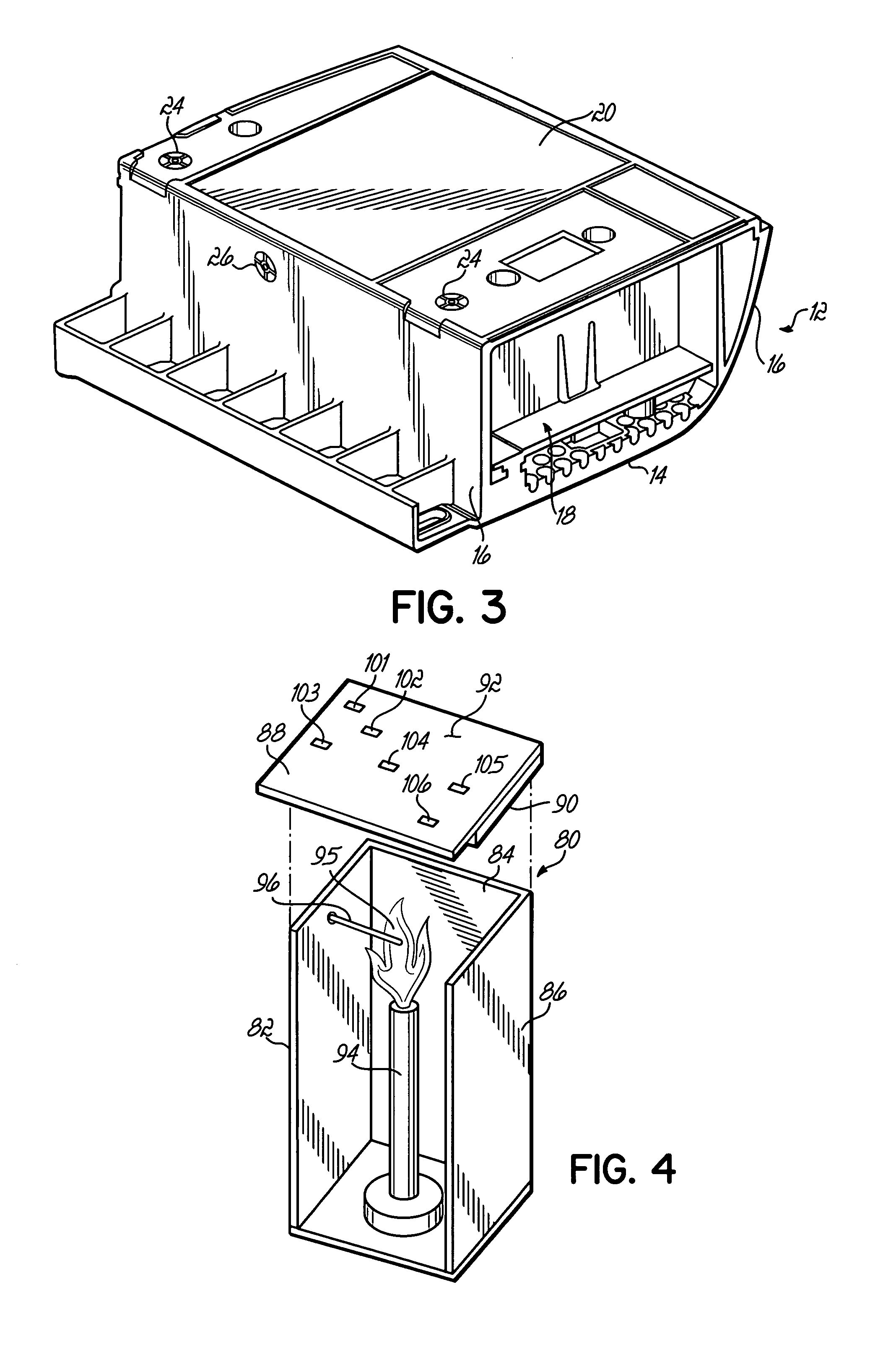
[0009] A battery case is provided that is made of an intumescent flame retardant polymeric composition that provides fire shielding, thermal shielding and a low heat release rate. To that end, a fire resistant additive is blended with a base polymer, which may include many types of thermoplastic and thermoset polymers, to produce a flame retardant polymeric material that is molded into a base portion and a cover portion to form the battery case of the present invention with good physical properties in addition to good flammability performance. In one embodiment of the present invention, one or more vent holes are provided in the battery case, advantageously in the cover portion, to permit gases that are generated during a thermal incident to escape from the battery compartment to thereby reduce pressure build-ups. In another embodiment of the present invention, an intumescent flame retardant polymeric composition is used to make one or more internal structural components to quench fires within the battery case.

Problems solved by technology

Thus, flame retardant systems have been developed for use with plastics, such as polyethylene, that attempt to provide intumescence, low heat release rate and low flame spread rate without decreasing the strength, durability, and impact and chemical resistance of the plastic to unacceptable levels for particular applications.
Invariably, however, some loss in the physical properties of the polymeric material is experienced upon addition of inorganic flame retardant materials to the polymer matrix.
However, the materials described therein contain a halogen material, namely, chlorinated polyethylene, which may generate corrosive HX gases, such as HCl.
These toxic by-products are dangerous to persons exposed thereto.
However, because they are environmentally unfriendly, it is desirable to find alternative fire retardant systems that do not use halogens.
Under unusual and abusive circumstances, fire “incidents” can occur during use of batteries, for example, lithium batteries.

Method used


Image

  • Fire shielding battery case
  • Fire shielding battery case
  • Fire shielding battery case

Examples


examples

[0044] Table 1 lists a general formulation of a non-halogenated fire resistant additive that may be added to different base polymers to make intumescent flame retardant polymers for the battery case 10 of the present invention. The components and the amounts of each component have been further described in detail above. Table 1 also lists four exemplary formulations 1-4 in accordance with this embodiment of the present invention.

TABLE 1GeneralFormu-Formu-Formu-Formu-Formu-Ingredientslationlation 1lation 2lation 3lation 4HDPE20-45 131 302 303 273Polyolefin Copolymer 304 135 134 11.74Nitrogenous 5-25 176 257 86 7.26Gas-Generating Agent 177 15.37Water10-35 228 228 228 19.88Vapor-Generating Agent 89 109Antioxidant1-5 110 110 110 0.910 111 111 111 0.911Reinforcing Agent 0-15 812 812 812 7.212Total100100100100100

1Fortiflex ® T50-2000 from BP Solvay Polyethylene North America, Houston, TX.

2Finathene ® WR 201 from Atofina Petrochemicals, Houston, TX.

3Paxon ® BA46-055 from ExxonMobil Che...


PUM


Abstract

A battery case made of an intumescent flame retardant polymeric composition that provides fire shielding, thermal shielding and a low heat release rate. A fire resistant additive is blended with a base polymer to produce the flame retardant polymeric material that is molded into the battery case. In one embodiment, one or more vent holes are provided in the battery case, advantageously in the cover portion, to permit gases to escape. In another embodiment, the fire resistant additive used for the battery case composition comprises a polymeric binder that includes an α-olefin-containing copolymer and a high density polyethylene, a nitrogenous gas-generating agent; a water vapor-generating agent; an antioxidant; and optionally a reinforcing agent. In another embodiment, the base polymer comprises a polyphenylene oxide and polypropylene blend, unfilled or filled with up to 60 wt. % glass fiber.

Description

CROSS REFERENCE TO RELATED APPLICATION [0001] This application is related to commonly owned, co-pending U.S. patent application Ser. No. ______ (Attorney Docket No. DP-309400) filed on even date and entitled “Halogen-Free Fire Retardant System For Low Heat Release Polymers,” the disclosure of which is incorporated herein by reference in its entirety as if completely set forth herein below.TECHNICAL FIELD [0002] This invention relates to a battery case made with an intumescent flame retardant polymeric material. BACKGROUND OF THE INVENTION [0003] Intumescent materials contain ingredients that decompose on severe heating to generate gases and form an incombustible or low combustible residue. The expelled gases expand the residue to form a foam layer with improved thermal insulation properties. Materials also having a low heat release rate are advantageous in that once they are exposed to fire they release less heat to neighboring materials and diminish fire propagation. Low heat relea...

Claims


Application Information

Patent Timeline
IPC IPC(8): H01M50/112H01M50/117H01M50/121H01M50/122H01M50/143
CPCH01M2/0242H01M2/0257H01M2/1235H01M2/1094H01M2/0277Y02E60/10H01M50/112H01M50/24H01M50/342H01M50/121H01M50/117H01M50/122H01M50/143
Inventor ABU-ISA, ISMAT ALIWATERS, JOHN EUGENE
Owner ENERDEL
Learn More