Laborsaving and safety cigarette lighter
a technology of cigarette lighters and lighters, which is applied in the field of electronic cigarette lighters, can solve the problems of laborious operation of current available lighters, inability to reduce the force needed to press the button difficulty in operation of currently available piezoelectric lighters, so as to improve the feeling of operation of electronic (piezoelectric) direct connection lighters and facilitate the pressing of the lighter's button
- Summary
- Abstract
- Description
- Claims
- Application Information
AI Technical Summary
Benefits of technology
Problems solved by technology
Method used
Image
Examples
example 1
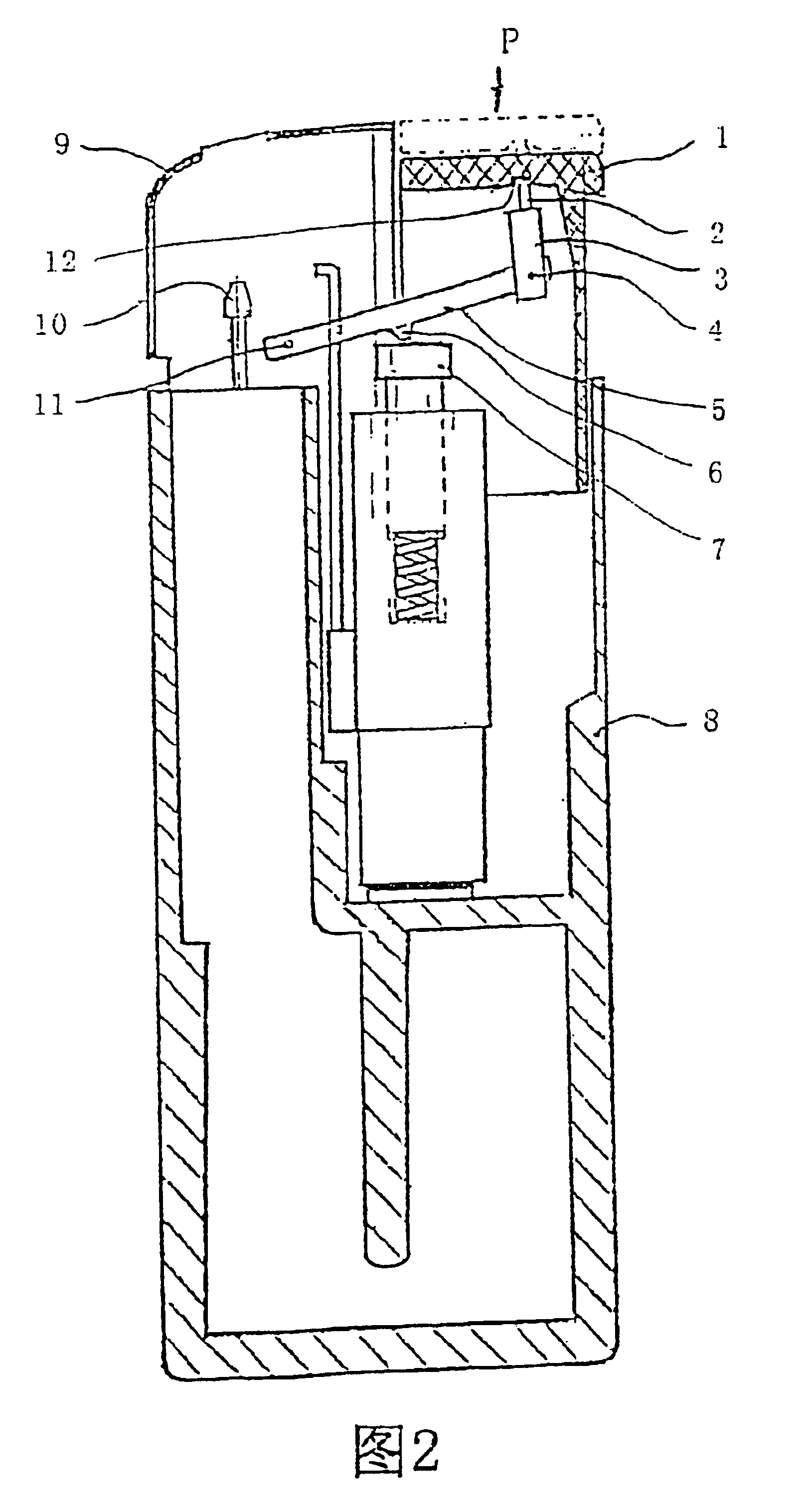
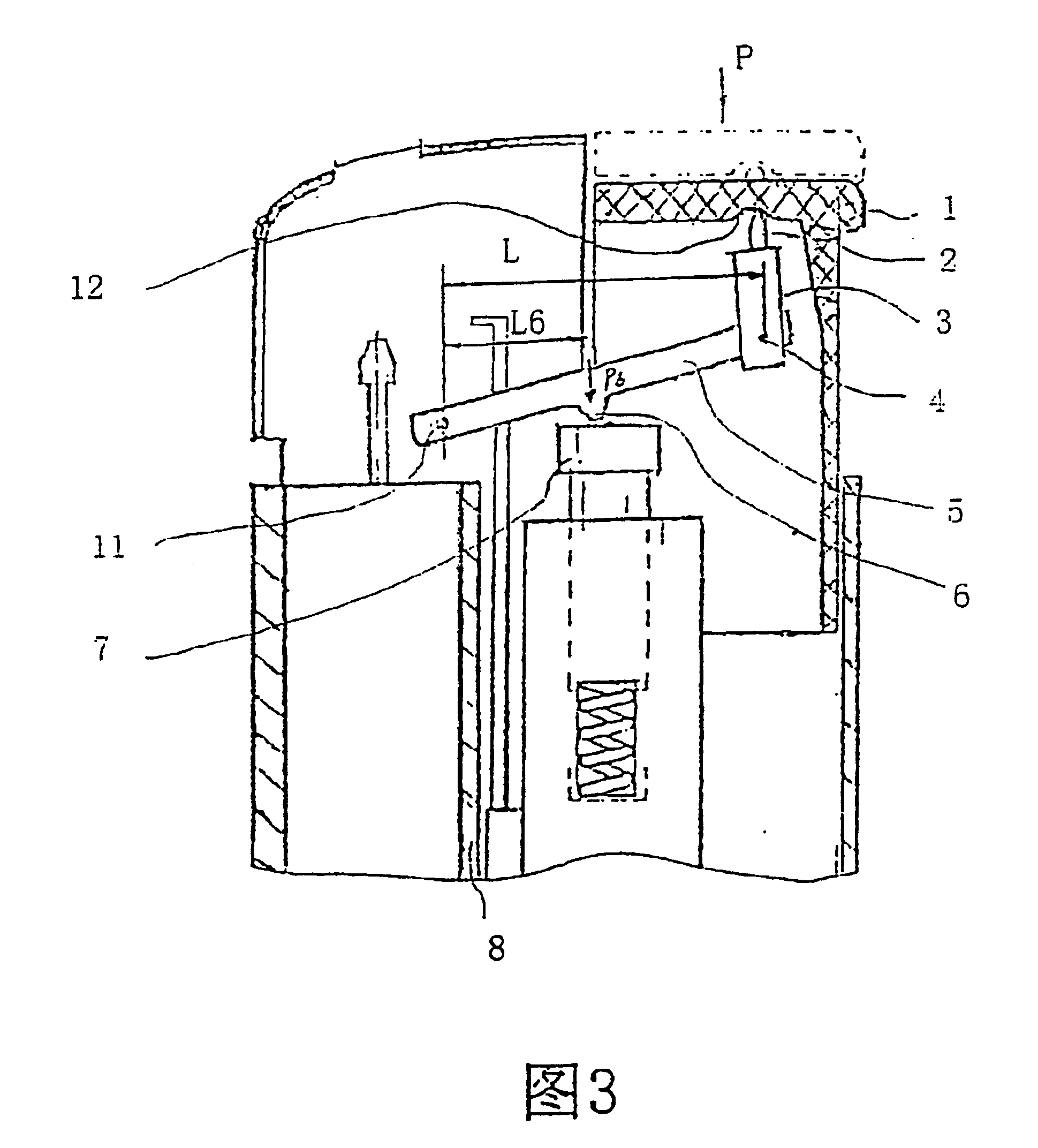
[0046]FIG. 2 and FIG. 3 illustrate a physical example of this invention. As shown in FIG. 2, the whole assembly of the lighter's force reduction device is enclosed in casing 8. it consists of lever 5, and there is an active point 4 on each end of lever 5, a fixed point 11 and a middle point 6 with pivot. One of the lever's active points 4 is connected to the end of connecting rod 3 with a movable pin (not illustrated) so that the parts can turn. The active point on lever 5 functions as a pivot for moment transfer. There is a long and thin fulcrum lever 2 at the other end of connecting rod 3, and the fulcrum rod can be named as button connecting rod fulcrum rod.
[0047] Fulcrum rod 2 contacts with concave cambered surface 12 of button 1. cambered surface 12 and button connecting rod fulcrum rod 2 can be regarded as spot contact or adjacent, which is designed to ensure the optimum dexterity for the lever mechanism of this invention. The other end's fixed point 11 of the said lever 5 is...
example 2
[0051] As is shown in FIG. 4-7, the example is a safe and laborsaving lighter, which is one of the selected examples from the invention.
[0052] The lighter consists of casing 101, fuel tank 102 in casing 101, piezoelectric assembly and gas release assembly as well as windshield 114. casing 101 serves as the fuel tank wall. The piezoelectric assembly consists of piezoelectrics 103, piezoelectric push rod 104 and button 105. The gas release assembly consists of release needle 115, release valve 116 and adjustment ring 117. There is a pry board 113 between the gas release assembly and piezoelectric assembly for linkage of them. On the end face of button 105 there is a longitudinal slot opening 106, in which rests L-shaped safety piece 107. There is a return spring 120 between the sidewall of safety piece 107 and button 105. There is rocker arm 109 above fry board 113 to safety piece 107.
[0053] On each side of rocker arm 109 there are cam 110a and 110b. The lower part 107a of safety pi...
example 3
[0058] See also FIG. 8. Example 3 is the same as example 2 but the rocker arm. Rocker arm 109′ in this example adopts the structure as shown in FIG. 8. Compared with rocker arm 109 in example 2, rocker arm 109′ in this example has only one cam 110′ on its right side. In normal state, the lower part 107a of safety piece 107 rests on cam 110′ of rocker arm 109′. The other structure and operation principle in this example are the same as those in example 2.
PUM
 Abstract
Description
Claims
Application Information
 - R&D
- Intellectual Property
- Life Sciences
- Materials
- Tech Scout
- Unparalleled Data Quality
- Higher Quality Content
- 60% Fewer Hallucinations
Browse by: Latest US Patents, China's latest patents, Technical Efficacy Thesaurus, Application Domain, Technology Topic, Popular Technical Reports.
© 2025 PatSnap. All rights reserved.Legal|Privacy policy|Modern Slavery Act Transparency Statement|Sitemap|About US| Contact US: help@patsnap.com


