[0008]The object is also achieved with a
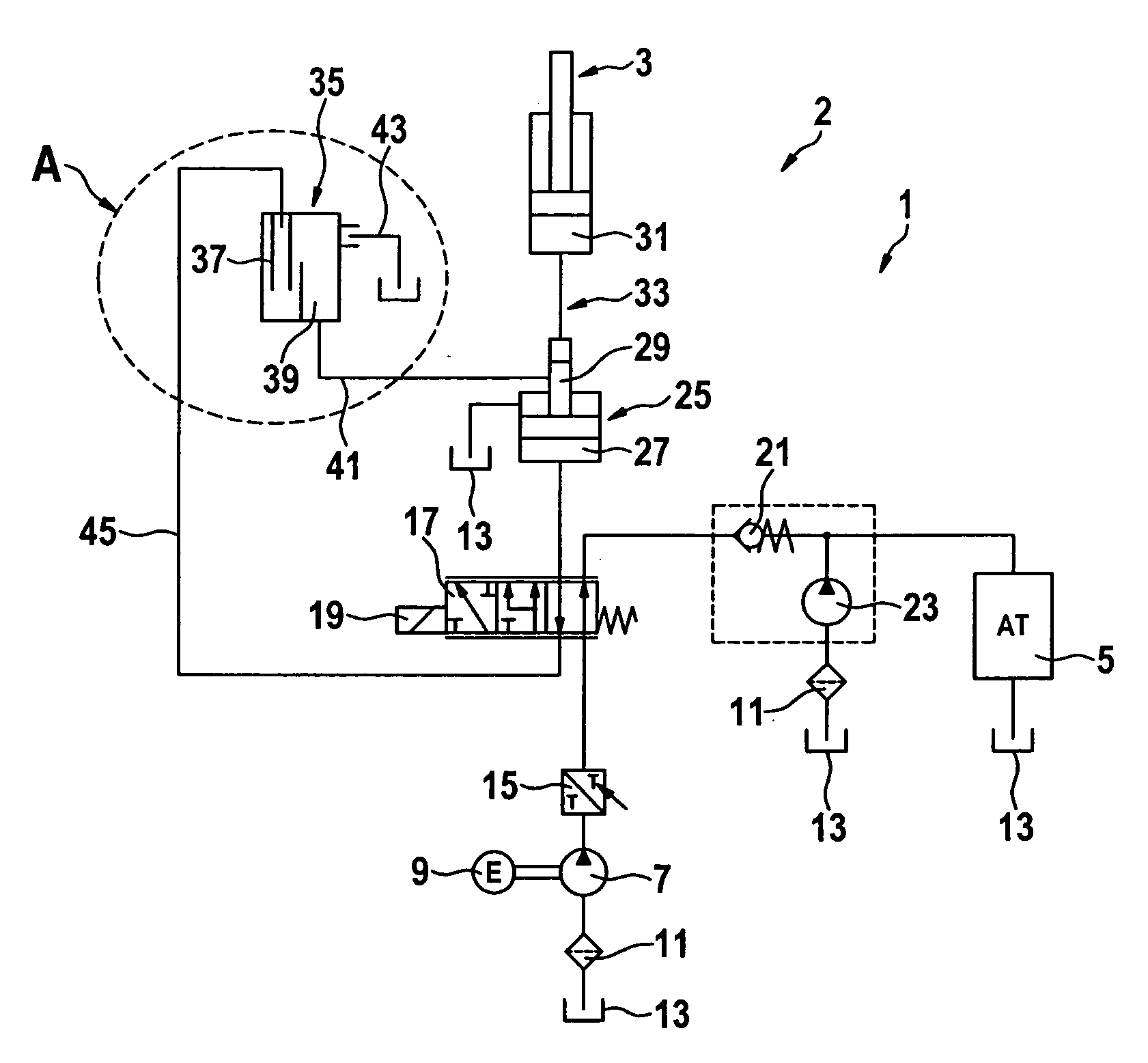
hydraulic circuit for controlling a hybrid clutch and an automatic transmission of a motor vehicle, and having an electrically operated hydraulic pump to supply the hybrid clutch and the automatic transmission with a hydraulic medium. A pressure booster is connected downstream of the hydraulic pump, with a pressure booster slave cylinder and a pressure booster master cylinder, a hydraulic line segment connected between the pressure booster and the hybrid clutch, with the pressure booster master cylinder and a hybrid clutch slave cylinder to actuate the hybrid clutch. An
energy storage device is provided that can be connected into the circuit to store, receive, and / or feed in hydraulic energy. When operating the motor vehicle, it can be desirable to disengage the hybrid clutch as quickly as possible. Comparatively large quantities of hydraulic energy are required to achieve that result. Advantageously, at least part of the comparatively large but only briefly needed quantity of energy can be supplied by the connected
energy storage device. That makes it possible to advantageously reduce peak power demands on the electrically operated hydraulic pump. In the ideal case, nearly constant electrical
power consumption by the electrically operated hydraulic pump can be achieved. Advantageously, the electrically operated hydraulic pump can be designed comparatively smaller or less powerful. That applies both to the maximum possible
transport volume and also to the maximum
power consumption of an
electrical drive source attached to the electrically operated hydraulic pump, for example an
electric motor. In situations in which little or no power is needed by other hydraulic components of the hydraulic
system, the connected
energy storage device can be charged by the electrically operated hydraulic pump. Overall, comparatively economical use of electrical energy is possible.
[0009]The object is also achieved with a hydraulic circuit for controlling a hybrid clutch and an automatic transmission of a motor vehicle, and having an electrically operated hydraulic pump to supply the hybrid clutch and the automatic transmission with a hydraulic medium. A pressure booster is connected downstream of the hydraulic pump with a pressure booster slave cylinder and a pressure booster master cylinder. A hydraulic line segment is connected between the pressure booster and the hybrid clutch, with the pressure booster master cylinder and a hybrid clutch slave cylinder connected to actuate the hybrid clutch. A mechanically driven hydraulic pump is provided to supply the automatic transmission with the hydraulic medium. Conventional vehicles without hybrid components usually have automatic transmissions or multistage automatics with hydraulic actuation. Since those transmissions do not need any hydraulic actuation when the
internal combustion engine is shut off, they normally have a mechanically driven hydraulic pump. It is possible to advantageously combine such an automatic transmission having hybrid components, in particular hydraulically actuated hybrid components, with an electrically operated hydraulic pump. When the
internal combustion engine is shut off, and therefore the mechanically driven hydraulic pump is also shut off, the electrically operated hydraulic pump can advantageously take over supplying the automatic transmission with hydraulic energy, so that the hydraulic actuation
system for the automatic transmission is functional even when the
internal combustion engine is shut off. The electrically operated hydraulic pump thus takes over external supply of the automatic transmission with the hydraulic medium. Advantageously, that necessitates merely small modifications to already existing automatic transmissions. When the internal
combustion engine is running, on the other hand, valuable electrical energy can be saved by operating the mechanically driven hydraulic pump.
[0010]Finally, the object is achieved with a hydraulic circuit for controlling a hybrid clutch and an automatic transmission of a motor vehicle, and having an electrically operated hydraulic pump to supply the hybrid clutch and the automatic transmission with a hydraulic medium. A pressure booster is connected downstream of the hydraulic pump, the booster including a pressure booster slave cylinder and a pressure booster master cylinder. A hydraulic line segment is connected between the pressure booster and the hybrid clutch, with the pressure booster master cylinder and a hybrid clutch slave cylinder connected to actuate the hybrid clutch. A
heat exchanger is provided to dissipate
waste heat from an
electric motor of the electrically operated hydraulic pump into the hydraulic medium. Advantageously, the
electric motor of the electrically operated hydraulic pump can be protected against overheating. To that end, the hydraulic medium can be passed completely through the
heat exchanger before it is fed to the other components of the hydraulic circuit. In so doing, it can absorb the
waste heat produced by the electrically operated hydraulic pump. To that end, the hydraulic medium can advantageously be routed past thermally relevant zones of the electrically operated hydraulic pump housing or of the
electric drive, but without flooding the interior of the electric motor. The electric motor can advantageously be of smaller and more economical design.
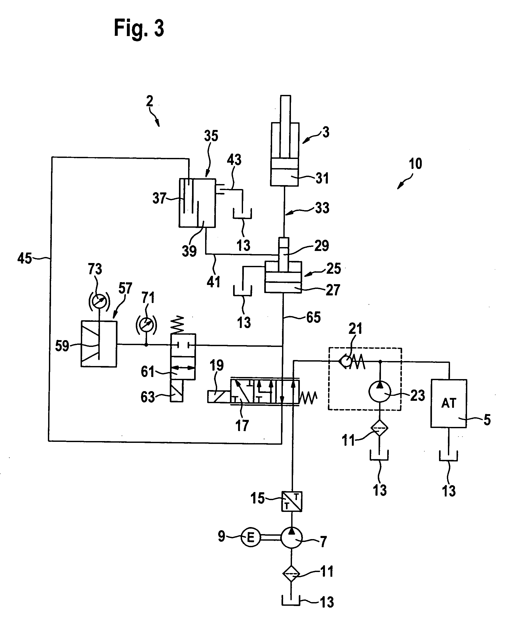
[0013]Other preferred exemplary embodiments of the invention are characterized by the fact that a
check valve is connected between the electrical and the mechanically driven hydraulic pumps to prevent
backflow from the mechanically driven hydraulic pump to the electrically operated hydraulic pump. Advantageously, it is thus guaranteed that when the automatic transmission is operated normally, i.e., when the internal
combustion engine is turned on, no
backflow of the hydraulic medium in the direction of the electrically operated hydraulic pump can occur. Advantageously, that also guarantees that the electrically operated hydraulic pump can be turned off if it is not needed, i.e., if the hybrid clutch is not disengaged, for example. Advantageously, that allows electrical energy for operating the electrically operated hydraulic pump to be saved.
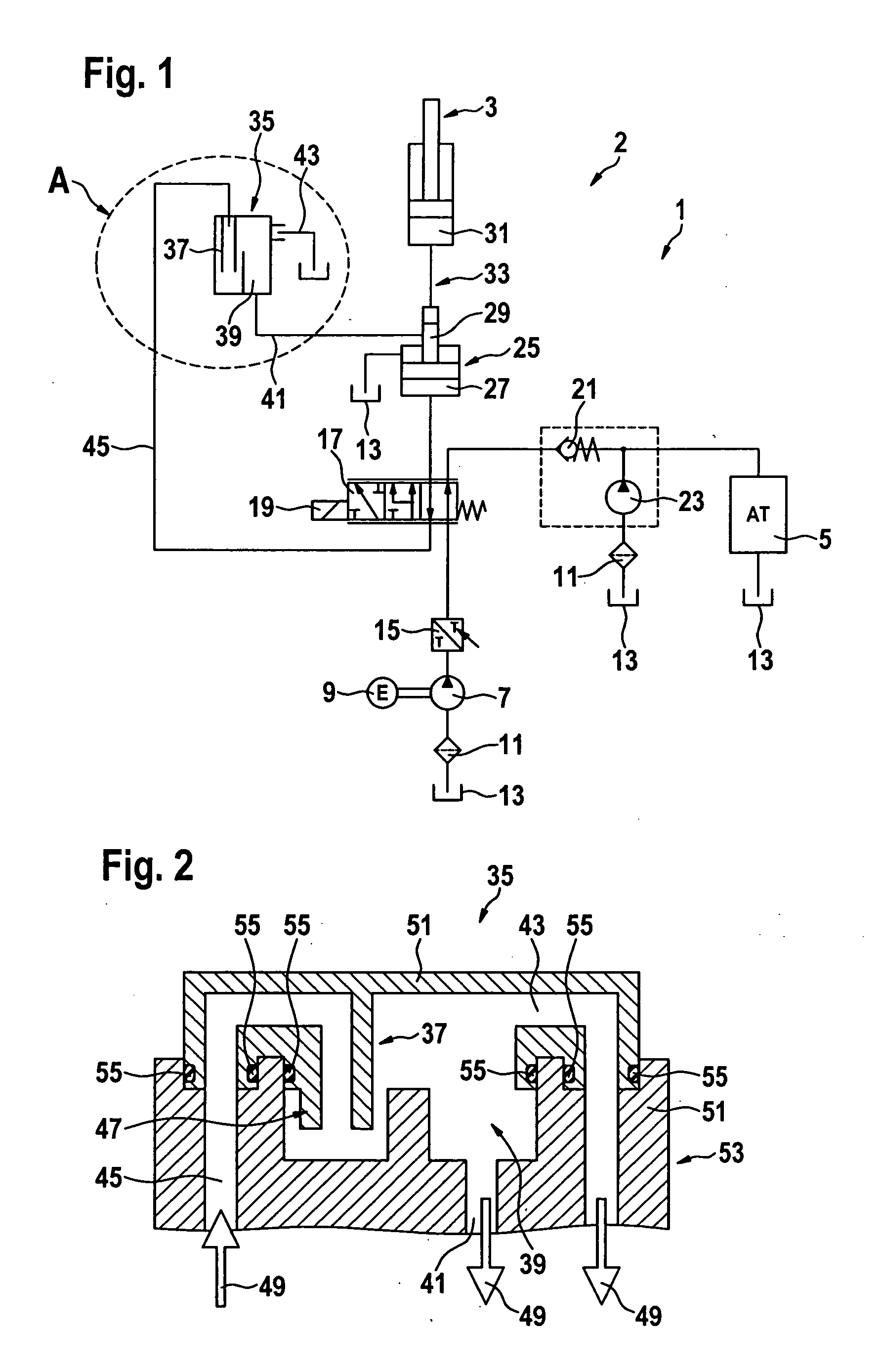
[0016]Other exemplary embodiments are characterized by the fact that the energy storage device has a disk spring storage device. Disk spring storage devices are economical to produce, and can store hydraulic medium against the reset force of the disk spring under a certain pressure.

