
Power supply management

a technology for power supply management and power supply, applied in the direction of power network operation system integration, position/direction control, ac network voltage adjustment, etc., can solve the problems of increased cost of sub-stations, inflated price, and increased power supply suppliers having to purchase extra energy at increased cost to meet these possible, so as to reduce the peak power demand and reduce the overall peak power demand

Inactive Publication Date: 2015-10-15
STEWART GARRY RICHMOND
View PDF30 Cites 2 Cited by
  • Summary
  • Abstract
  • Description
  • Claims
  • Application Information

AI Technical Summary

Benefits of technology

The patent describes a way to control the use of high-power devices in a way that reduces peak power demand on a power supply network. This is achieved through a data-communication network that allows users to be connected and allocated usage time slots for their high-power devices based on demand. This results in a reduction of overall peak power demand and better efficiency of the power supply network.

Problems solved by technology

As a consequence, a peak demand or power requirement surge has always been problematic and thus expensive to accommodate, resulting in the power suppliers having to purchase extra energy at increased cost to meet these possible peaks or surges.
These sub-plants are costly due to still requiring maintenance and upkeep even when sitting idle, along with fossil fuels to be purchased at or close to the time of operation, and thus being at an inflated price.
Furthermore, this increases the discharge into the environment of damaging greenhouse gasses.
In the event that sub-plants are not utilised, then the power stations themselves have to be initially constructed to meet the difficult-to-predict peak power demands, leading to a much more costly infrastructure.
However, the actual implementation of such a smart-grid system and the processes therebehind have not to date been fully explored.

Method used


Image

  • Power supply management
  • Power supply management
  • Power supply management

Examples


Embodiment Construction

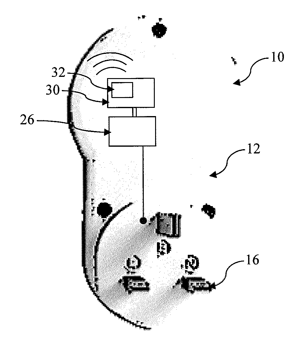
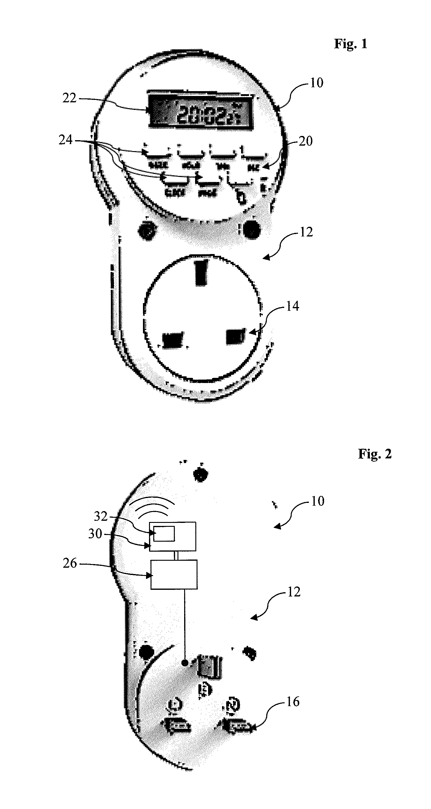
[0017]Referring firstly to FIGS. 1 and 2 of the drawings, there is shown one example of an electronic-data-network controller 10 which comprises a controller housing 12 having an appliance socket 14 at one side, in this case being a front side, and wall-socket plug 16 at another side, in this case being the back side of the housing 12 and opposite the appliance socket 14. The appliance socket 14 is adapted to receive an electrical plug of an appliance, and the wall-socket plug 16 is adapted to be received in a wall socket providing an electrical outlet and interfacing with a mains electricity power grid 18.

[0018]The controller housing 12 is, for example, a two part, preferably moulded plastics, housing which is hollow or substantially hollow to enable the required circuitry to be incorporated. The housing 12 in this case is elongate and cuboidal for ease of use, but other shapes can be considered, such as circular, cylindrical, and spherical.

[0019]A user interface 20 is provided on ...


PUM


Abstract

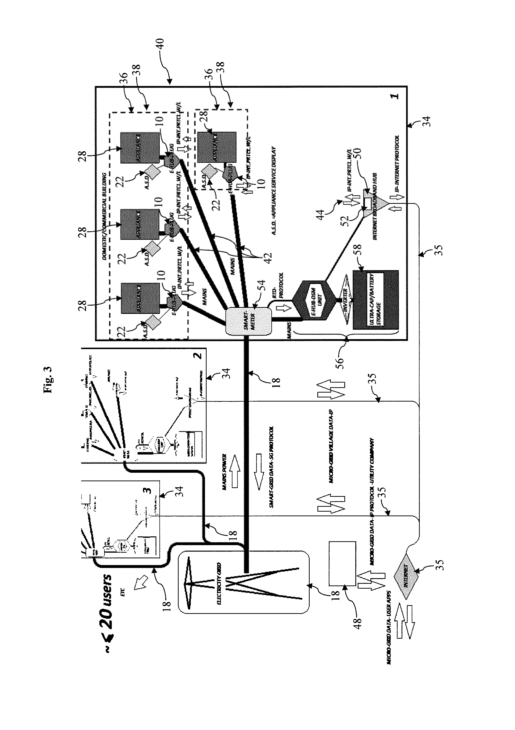
A method of reducing peak power demand on a mains-grid power supply network, comprises the steps of: a] providing a data-communication network by which a plurality of users being fed by the power supply network are communicable; b] connecting a controller associated with at least a high-power-demand electrical device of each user to the data-communication network; and c] dynamically allocating via the data-communication network a usage time slot for energization of said high-power-demand device based on demand, whereby usage of said high-power-demand devices associated with the data-communication network is controlled thereby enabling a reduction in overall peak power demand. An electronic-data-network controller and a power-supply management system are also provided.

Description

CROSS-REFERENCE TO RELATED APPLICATIONS[0001]This application claims priority from British patent application number GB 1406759.9, entitled “Improvements in or Relating to Power Supply Management”, which was filed on 15 Apr. 2014, the contents of which are hereby incorporated by reference for any purpose in their entirety.FIELD OF THE TECHNOLOGY[0002]The present invention relates to a method of reducing peak power demand on a mains-grid power supply network, to an electronic-data-network controller which is specifically adapted for use with the said method, and to power-supply management system incorporating one or more of the said controllers and / or the said method.BACKGROUND OF THE INVENTION[0003]The traditional mains power supply grids provide a centralized, producer-controlled electricity network which is reactive to demand rather than being proactive. As a consequence, a peak demand or power requirement surge has always been problematic and thus expensive to accommodate, result...

Claims


Application Information

Patent Timeline
Patent Type & Authority Applications(United States)
IPC IPC(8): H02J3/00G05B15/02
CPCG05B15/02H02J3/00Y02B70/3225Y04S20/222Y04S20/242H02J2310/14H02J13/00004H02J3/14Y02B70/30H02J13/0005H02J13/00028
Inventor STEWART, GARRY RICHMOND
Owner STEWART GARRY RICHMOND
Learn More