

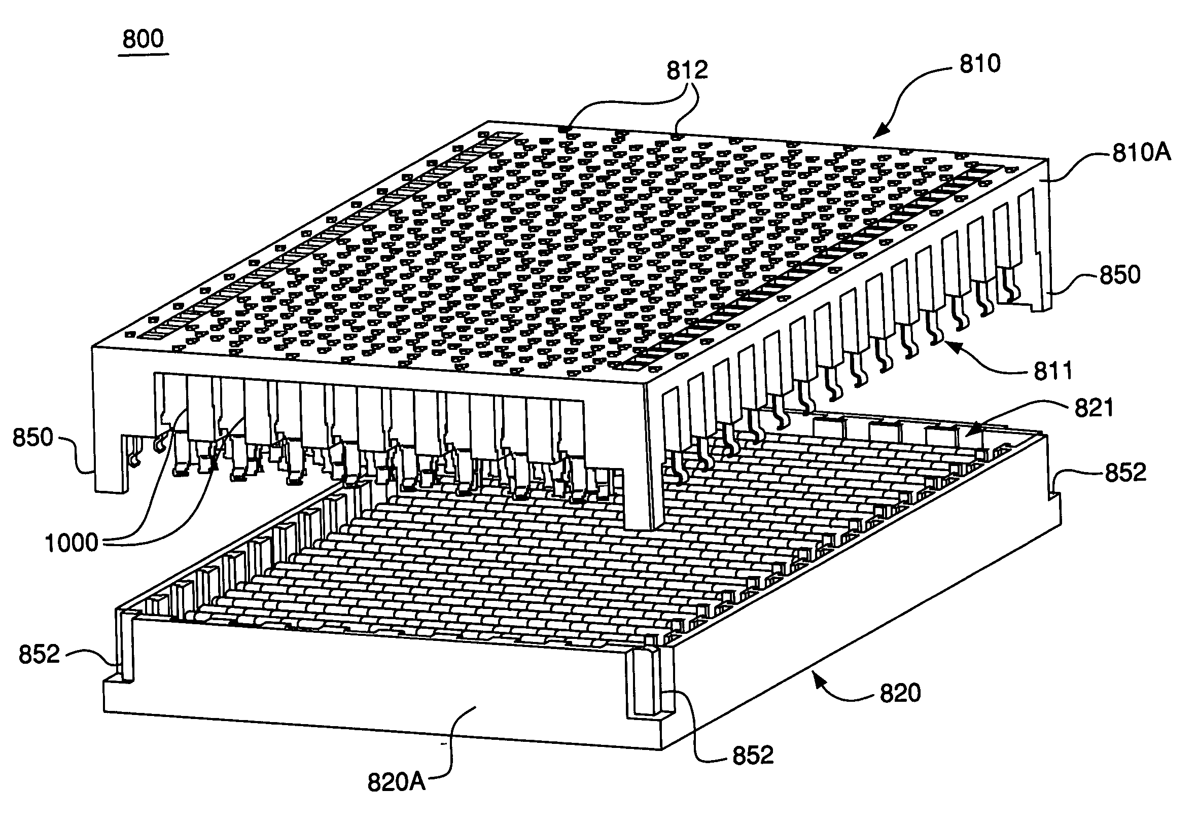
High speed electrical connector without ground contacts
a high-speed electrical connector and ground contact technology, applied in the direction of coupling device connection, connection contact member material, coupling device details, etc., can solve the problems of compromising signal integrity, limiting contact density (and, therefore, connector size), and unsatisfactory interference, etc., to achieve low-weight high-speed and limit the level of cross-talk
- Summary
- Abstract
- Description
- Claims
- Application Information
AI Technical Summary
Benefits of technology
Problems solved by technology
Method used
Image

Examples
Embodiment Construction
[0026] Certain terminology may be used in the following description for convenience only and should not be considered as limiting the invention in any way. For example, the terms “top,”“bottom,”“left,”“right,”“upper,” and “lower” designate directions in the figures to which reference is made. Likewise, the terms “inwardly” and “outwardly” designate directions toward and away from, respectively, the geometric center of the referenced object. The terminology includes the words above specifically mentioned, derivatives thereof, and words of similar import.
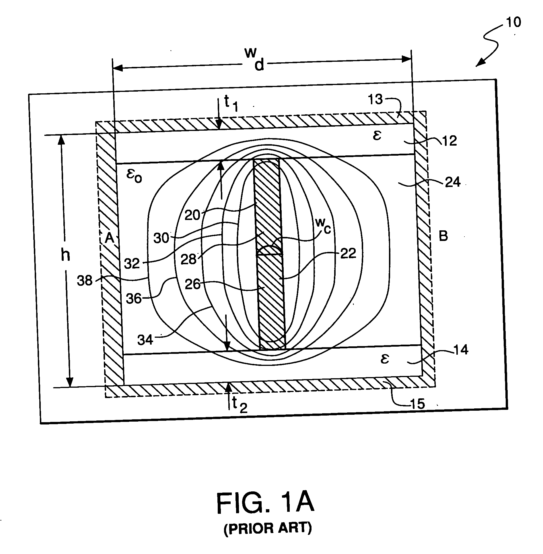
[0027]FIG. 1A is a schematic illustration of an electrical connector in which conductive and dielectric elements are arranged in a generally “I” shaped geometry. Such connectors are embodied in the assignee's “I-BEAM” technology, and are described and claimed in U.S. Pat. No. 5,741,144, entitled “Low Cross And Impedance Controlled Electric Connector,” the disclosure of which is hereby incorporated herein by reference in its entirety....
PUM
 Abstract
Description
Claims
Application Information