Method of setting wireless communication device

Active Publication Date: 2005-08-04
138 EAST LCD ADVANCEMENTS LTD
View PDF14 Cites 20 Cited by
  • Summary
  • Abstract
  • Description
  • Claims
  • Application Information

AI Technical Summary

Benefits of technology

[0006] The object of the invention is thus to provide a technique of rea

Problems solved by technology

The operation of setting the new communication device is generally time and labor consuming.
It is especially troublesome to set a communic

Method used


Image

  • Method of setting wireless communication device
  • Method of setting wireless communication device
  • Method of setting wireless communication device

Examples


Embodiment Construction

[0031] One mode of carrying out the invention is discussed below as a preferred embodiment in the following sequence: [0032] A. General Configuration [0033] B. Structure of Functional Blocks [0034] C. Setting Process for Wireless Communication [0035] D. Modifications

A. General Configuration

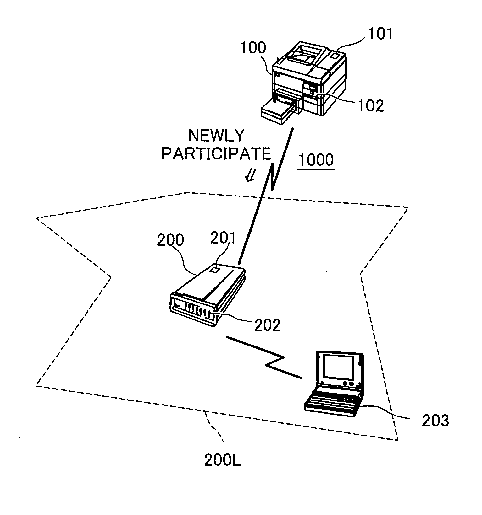
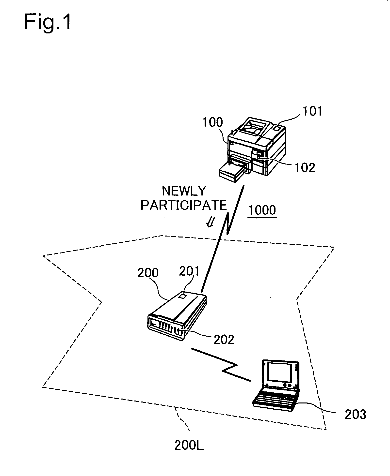
[0036]FIG. 1 schematically illustrates the configuration of a communication system 1000 including a printing device 100 and a relay station 200. The relay station 200 is an access point of an infrastructure wireless LAN (Local Area Network) or wireless network 200L. A personal computer (PC) 203 participates as one station in this wireless network 200L. Both the relay station 200 and the PC 203 have configuration information including an SSID (Service Set Identifier) and an encryption key of WEP (Wired Equivalent Privacy) to establish wireless communication in the wireless network 200L. In the description hereafter, this configuration information is referred to as ‘LAN configuration information’...


PUM


Abstract

A relay station 200 constructs an infrastructure wireless network 200L. A printing device 100 requests new participation in the wireless network 200L. When preset conditions are satisfied, for example, when the user has pressed a push button 201 provided on the relay station 200, the relay station 200 establishes temporary wireless communication with the printing device 100 and changes an SSID of the printing device 100 to an SSID of the relay station 200. In this manner, this arrangement readily changes the configuration information of the printing device 100.

Description

BACKGROUND OF THE INVENTION [0001] 1. Field of the Invention [0002] The present invention relates to a technique of setting a wireless communication device to establish wireless communication. [0003] 2. Description of the Related Art [0004] Various forms of wireless communication are widely used for data transmission between information processing devices. The typically available form of wireless communication is a wireless LAN (Local Area Network) in conformity with the IEEE 802.11 standard as disclosed in, for example, Japanese Patent Laid-Open Gazette No. 2003-283506. General requirement for wireless communication is common settings in communication devices that establish communication. For example, in an infrastructure wireless LAN, an SSID (Service Set Identifier) and an encryption key of WEP (Wired Equivalent Privacy) are commonly set to respective communication devices functioning as stations and access points. In an Ad Hoc wireless LAN, a channel and an encryption key of WEP...

Claims


Application Information

Patent Timeline
IPC IPC(8): H04B7/15H04B7/26H04L12/28H04W16/26H04W24/00H04W48/08H04W74/04H04W84/12
CPCH04W28/18H04W76/02H04W88/04H04W48/14G06F3/1231G06F3/1292H04W12/04G06F3/1205H04W84/047H04W76/10H04W12/50
Inventor SHIOHARA, SUSUMUISHIDA, HITOSHIKIYONO, TATSUYA
Owner 138 EAST LCD ADVANCEMENTS LTD
Why Eureka
Try Eureka