Liquid circulation type cooling system

a cooling system and liquid circulation technology, applied in the direction of lighting and heating apparatus, semiconductor/solid-state device details, domestic cooling apparatus, etc., can solve the problems of increasing the size of the cooling device, increasing the heat-generating amount of the cpu, and achieving the limit of heat radiation performance in the cooling devi

Inactive Publication Date: 2005-08-11
HITACHI CABLE
View PDF5 Cites 26 Cited by
  • Summary
  • Abstract
  • Description
  • Claims
  • Application Information

AI Technical Summary

Benefits of technology

[0025] According to the liquid circulation type cooling system of the present invention, the liquid reservoirs each for storing a liquid are disposed on the upstream and the downstream sides of the heat radiation space, respectively, and at least the liquid opening of the liquid reservoir positioned at the downstream side is filled always with the liquid. Thus, even if the liquid circulation type cooling system is positioned in the upside-down postures, it is possible to prevent that air flows into the system other than the liquid reservoir. As a result, electronic instruments may be positioned in the upside-down postures, so that an applicable scope for the liquid circulation type cooling system can be broadened.

Problems solved by technology

However, a cooling device of an air-cooling type requires a heat radiation area for a radiator in response to an amount of heat radiation, resulting in a disadvantage of increasing a size of the cooling device.
Besides, there is recently such a tendency that a heat-generating amount of a CPU increases accompanied with high-speed processability and multifunctionality required for electronic instruments.
In this respect, heat radiation performance reaches substantially a limit in a cooling device of an air-cooling type.

Method used


Image

  • Liquid circulation type cooling system
  • Liquid circulation type cooling system
  • Liquid circulation type cooling system

Examples


first embodiment

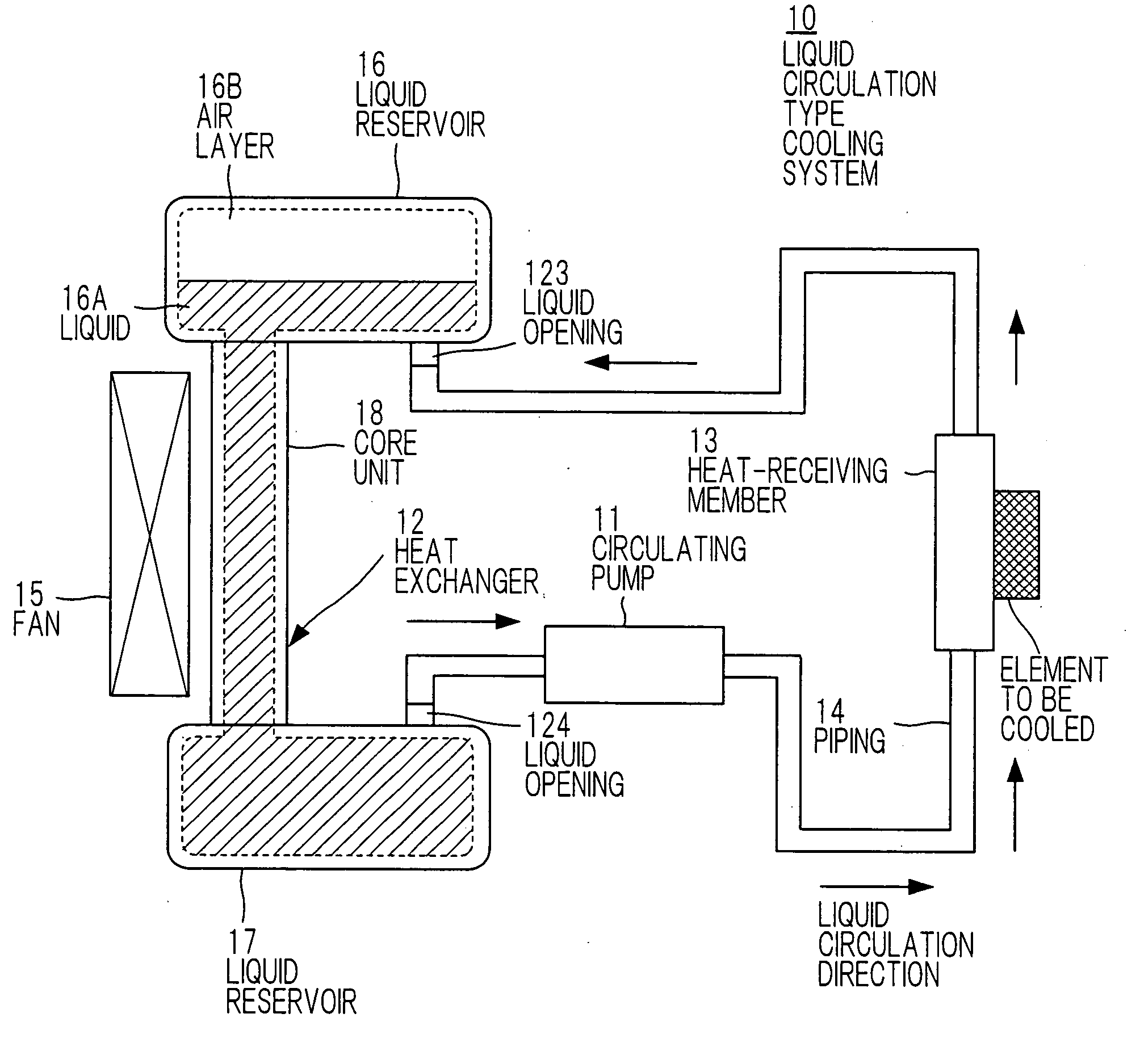
[0040]FIG. 3 is a schematic diagram showing a circuit of a liquid circulation type cooling system according to a first embodiment of the present invention wherein the liquid circulation type cooling system 10 includes a circulating pump 11 for circulating a liquid such as water, a heat exchanger 12 for radiating heat outside a casing for the system, the heat exchanger being disposed in a heat radiation space, a heat-receiving member 13 attached to an element to be cooled such as a heat-generating element, the heat-receiving member being served for transferring efficiently heat from the element to be cooled to the liquid, a piping 14 for connecting the above-mentioned components with each other, the piping being composed of a flexible tube or a fixed piping, and a fan 15 for supplying air to the heat exchanger 12 to achieve forced-air cooling.

[0041] The heat exchanger 12 has a core unit 18, a liquid reservoir 16 formed at the top of the core unit 18 in the vertical direction in the ...

second embodiment

[0058]FIG. 6 is a schematic diagram showing a circuit of a liquid circulation type cooling system according to a second embodiment of the present invention wherein the liquid circulation type cooling system 20 includes a circulating pump 21, for circulating a liquid, a heat exchanger 22 for radiating heat outside a casing for the system, the heat exchanger being disposed in a heat radiation space, a heat-receiving member 23 attached to an element to be cooled such as a heat-generating element, the heat-receiving member being served for transferring efficiently heat from the element to be cooled to the liquid, a piping 24 for connecting the above-mentioned components with each other, the piping being composed of a flexible tube or a fixed piping, and a fan 25 for supplying wind to the heat exchanger 22 to achieve forced-air cooling.

[0059] The heat exchanger 22 has a core unit 18, a liquid reservoir 26 formed on the left side with respect to the core unit 18 in the drawing, and anoth...

third embodiment

[0071]FIG. 9A is a side view showing a structure of a heat exchanger 32 used in a liquid circulation type cooling system according to a third embodiment of the present invention, and FIG. 9B is a plan view showing the heat exchanger 32 wherein the heat exchanger 32 is the one having a “corrugated straight fin core” type structure, which is composed of a core unit 18, a liquid reservoir 36 positioned on the left side to the core unit 18 in the drawing, and another liquid reservoir 37 positioned on the right side to the core unit 18.

[0072] The heat exchanger 32 has the same structure as that of the heat exchanger 22 except that the liquid reservoir 36 has a liquid opening 323 into and from which a liquid may be introduced and discharged on a side of the liquid reservoir 36 perpendicular to the side to which the core unit 18 is connected, while a liquid opening 324 which is the same as the liquid opening 323 is provided on a side of the liquid reservoir 37 perpendicular to the side to...


PUM


Abstract

A liquid circulation type cooling system includes a circulating pump for circulating a liquid, a heat exchanger disposed in a heat radiation space and for radiating heat outside the system. The heat exchanger contains a core unit, a liquid reservoir for storing the liquid positioned on the upstream side of the core unit and having a liquid opening, another liquid reservoir for storing the liquid and positioned on the downstream side of the core unit, the other liquid reservoir having a liquid opening, a heat-receiving member, a piping, and a fan for supplying air to the heat exchanger to effect forced air-cooling.

Description

[0001] The present application is based on Japanese patent application No. 2004-033761, the entire contents of which are incorporated herein by reference. BACKGROUND OF THE INVENTION [0002] 1. Field of the Invention [0003] The present invention relates to a liquid circulation type cooling system wherein a liquid is circulated in the system to transfer heat generated from a heat-generating element to a heat radiation space by means of the liquid thereby to radiate the heat, and particularly to a liquid circulation type cooling system mounted on an electronic instrument which may be positioned in the upside-down postures as a result of mounting the cooling system. [0004] 2. Description of the Related Art [0005] In recent years, high-performance electronic instruments have been developed, so that a heat-generating amount of, particularly, circuit parts such as CPU (Central Processing Unit) and electric power unit contained in a main body increases. In this connection, improvements in h...

Claims


Application Information

Patent Timeline
Patent Type & Authority Applications(United States)
IPC IPC(8): F25D17/02F25D9/00F28D15/02F28F1/30H01L23/473H05K7/20
CPCF28D15/00H01L23/473F28F2250/08H01L2924/0002H01L2924/00F28D15/0266H05K7/20
Inventor KITAJIMA, HIRONORISAKAYORI, HITOSHITAKAHASHI, TADASI
Owner HITACHI CABLE
Why Eureka
Try Eureka