Lifting foil

a foil and foil technology, applied in the field of fluid dynamics, can solve the problems of increasing commercial and governmental air transportation expenditures, high air transportation costs, and insufficiently satisfying techniques for dealing with induced drag, so as to achieve no substantial drag penalty, increase lift, and increase lift

Active Publication Date: 2005-08-11
HOUCK II RONALD G
View PDF30 Cites 45 Cited by
  • Summary
  • Abstract
  • Description
  • Claims
  • Application Information

AI Technical Summary

Benefits of technology

[0025] A still further object of the invention is to increase lift with no substantial drag penalty.
[0026] Other objects of the invention are to increase lift and decrease drag for very low speed flight, to reduce spanwise fluid ...

Problems solved by technology

The prior art shows numerous techniques for dealing with induced drag, but none are fully satisfactory.
It is an un...

Method used


Image

  • Lifting foil
  • Lifting foil
  • Lifting foil

Examples


Embodiment Construction

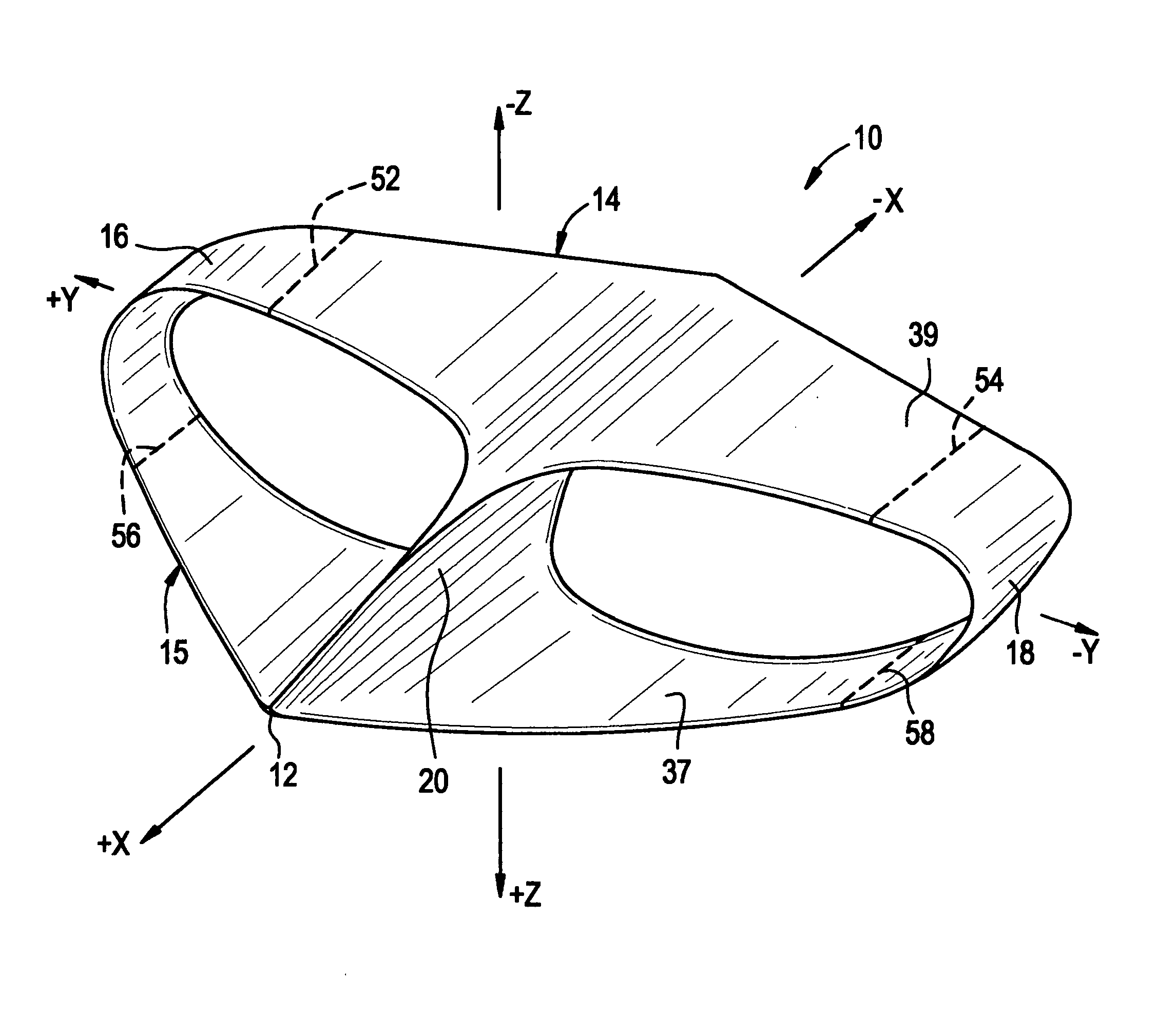
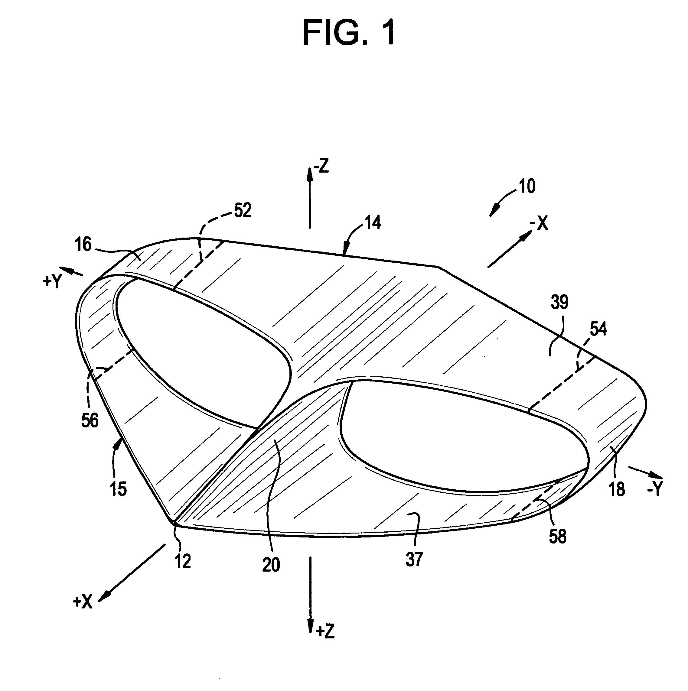
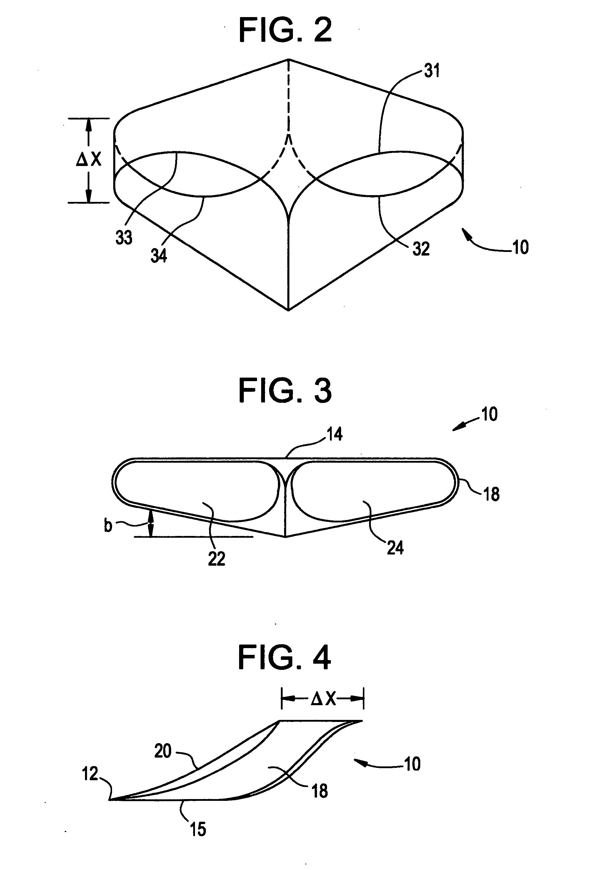
[0046] A preferred embodiment of the subject invention may have a form as generally illustrated by lifting foil 10 in FIGS. 1-4. FIG. 1 is a perspective drawing of the lifting foil with a coordinate system attached. The coordinate system has its origin at the center-of-gravity of foil 10. It is right-handed and employs conventional 3-axis, X,Y,Z Cartesian coordinate designations. Directions may also be referred to as “starboard” (+Y), “port” (−Y), “fore” (+X), “aft” (−X), “up” (−Z) and “down” (+Z). The term “spanwise” is used to refer to sideward motion in either the +Y or −Y direction. The lifting foil is laterally symmetrical across the X-Z vertical plane. FIG. 2 is a top view of lifting foil 10 while FIGS. 3 and 4 are front and side views respectively.

[0047] Lifting foil 10 comprises four basic elements, blended end-to-end to form a closed loop surrounding an open interior These elements are an upper course 14, a lower course 15, a starboard flow guide, 16 and a port flow guide ...


PUM


Abstract

A lifting foil for an aircraft, a hydrofoil or the like having a pair of courses or wings. Vortex losses due to spanwise fluid flow are substantially reduced by joining the tips of the courses with flow guides configured for jointly terminating the undesired flows. Termination is effected by providing the flow guides with crossections cambered for reducing the dynamic pressure of fluid flowing in a spanwise direction across flow guide surfaces.

Description

BACKGROUND OF THE INVENTION [0001] This invention relates generally to the field of fluid dynamics with emphasis on aerodynamic drag phenomena. A particular object of the invention is to reduce energy losses suffered by an aircraft in flight due to induced drag. It is known that this particular type of drag is accompanied by a shedding of vortices from the tips of the wings. It is believed that these vortices result from a spanwise flow of air from a relatively high pressure condition on the lower wing surface to a relatively low pressure condition on the upper wing surface. Similar phenomena occur around hydrofoils employed for underwater use. It might be remarked that air behaves much as a perfect fluid when acting against an airfoil at speeds below about 200 mph and at altitudes below about 100,000 ft. Within that regimen the mathematical tools employed for analysis of airfoils are substantially the same as those for hydrofoils General teachings regarding aircraft drag may be fou...

Claims


Application Information

Patent Timeline
IPC IPC(8): B63B1/24B64C3/16B64C3/38B64C39/06
CPCB63B1/248B64C3/16Y02T50/12B64C39/068B64C39/066Y02T50/10
Inventor HOUCK, RONALD G. II
Owner HOUCK II RONALD G
Why Eureka
Try Eureka