Vibration motor and mounting structure of the vibration motor and mounting method of the vibration motor

a technology of vibration motor and mounting structure, which is applied in the direction of supporting/enclosing/casing, electrical apparatus, dynamo-electric machines, etc., can solve the problems of increasing the number of processes, increasing the cost, and poor vibration transmittance or decrease the quantity, so as to increase the quantity of vibration transmitted, secure support, and the effect of effective production

Inactive Publication Date: 2005-08-11
TL ELECTRONICS CO LTD
View PDF24 Cites 3 Cited by
  • Summary
  • Abstract
  • Description
  • Claims
  • Application Information

AI Technical Summary

Benefits of technology

[0025] The above-described inventive support structure of the vibration motor has an advantage in that the vibration motor can be more securely supported thereby increasing the vibration quantity transmitted to the external.
[0026] Further, the above-described inventive support structure of the vibration motor has another advantage in which the vibration motor can be simply mounted thereby resulting in effective production thereof.

Problems solved by technology

However, a conventional support structure of the flat-typed vibration motor has a disadvantage in which a plurality of parts is employed thereby increasing the number of process.
Further, the conventional support structure has another disadvantage in which the number of parts is increased thereby resulting in a cost increase.
Furthermore, the conventional support structure has a still another disadvantage in which, though the vibration motor 10 is once again fixed on its upper side using the cushion pad 13, since the vibration motor is not stably fixed, as an operation period is totally lengthen, the vibration motor is separated from the boss thereby causing a poor vibration transmittance or decreasing the vibration quantity.
Additionally, the conventional support structure has a further disadvantage in which a user manually inserts all of the vibration motors into the boss in the vibration generation location, and in which, though automation installations are employed, the number of manufacture process is increased.

Method used


Image

  • Vibration motor and mounting structure of the vibration motor and mounting method of the vibration motor
  • Vibration motor and mounting structure of the vibration motor and mounting method of the vibration motor
  • Vibration motor and mounting structure of the vibration motor and mounting method of the vibration motor

Examples


Embodiment Construction

[0034] Hereinafter, preferred embodiments of the present invention will be described in detail with reference to the attached drawings.

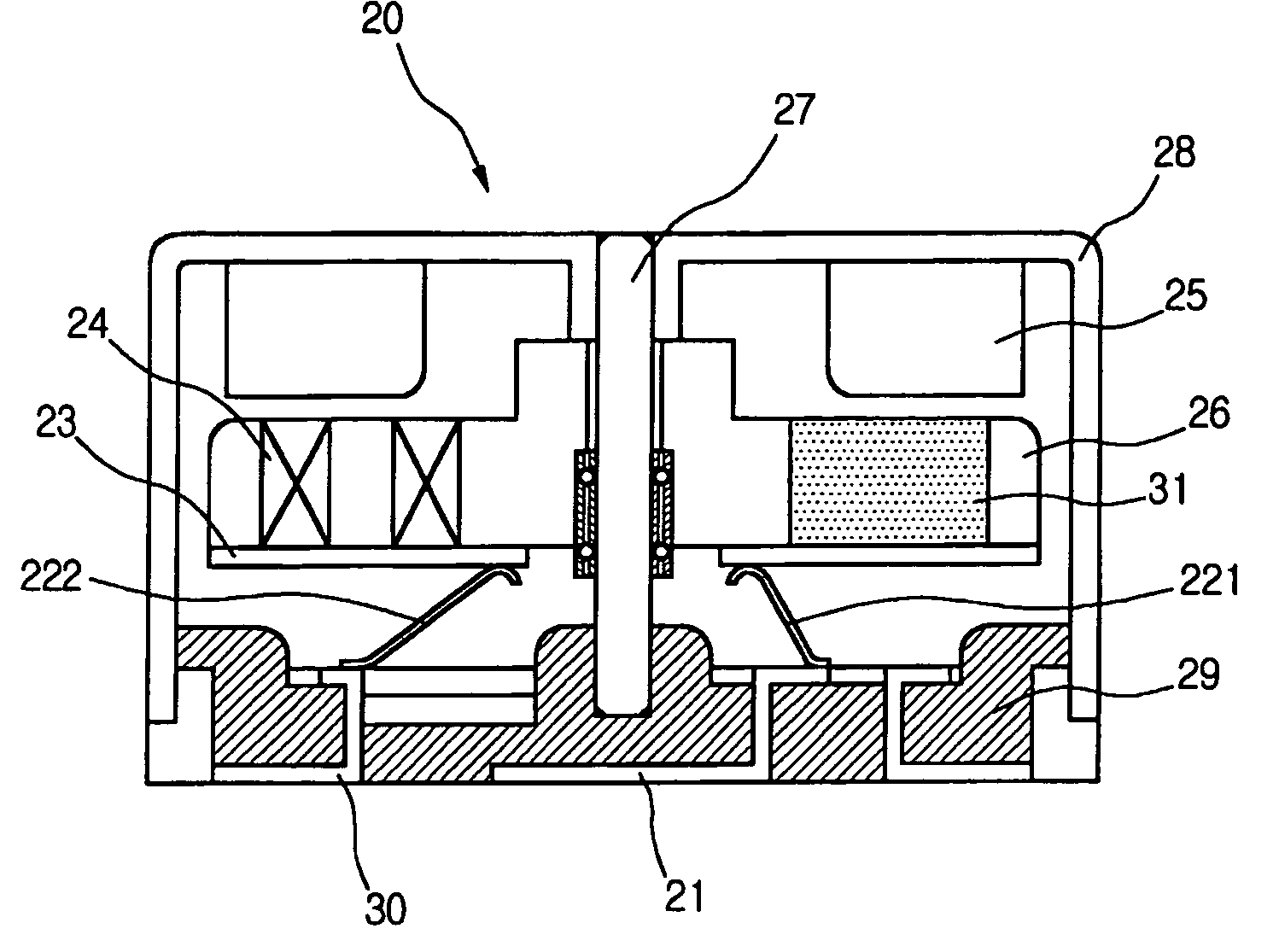
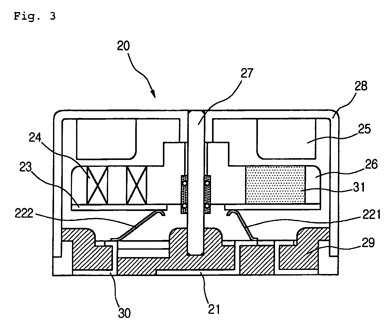
[0035]FIG. 3 is a sectional view illustrating a vibration motor and a mount structure thereof according to a preferred embodiment of the present invention.

[0036] Referring to FIG. 3, in a vibration motor, particularly, in a flat-typed vibration motor 20, unlike a conventional vibration motor, a structure modification of a lower housing is characterized.

[0037] In detail, first and second terminals 21 and 30 are formed on a lower side of the vibration motor 20 so as to be electrically connected with lower ends of brushes 221 and 222. Additionally, a base 29 is formed so as to fix the first and second terminals 21 and 30, and support a shaft 27.

[0038] In particular, the base 29 is molded of resin material, and preferably, the resin-material mold can be formed using an insert injection molding and at the same time, the first and second terminals 21 a...


PUM


Abstract

A vibration motor includes: a rotor having an eccentric gravity center; a shaft inserted through a bearing of the rotor; a magnet provided at a position facing the rotor, at least one commutator circumferentially formed on a lower surface of the rotor; at least one pair of brushes being in contact with the commutator; a first terminal and a second terminal connected with the one pair of brushes and exposed to the external at their lower sides so as to be in contact with an electric line; and a base as a mold for fixing the first terminal and/or the second terminal thereto.

Description

TECHNICAL FIELD [0001] The present invention relates to a vibration motor, and more particularly to a flat-typed vibration motor that can be simply fixed to a vibration generation location such as a portable phone or a pager only by easy working process, a mount structure of the flat-typed vibration motor and a mounting method for the flat-typed vibration motor. BACKGROUND ART [0002] Generally, a vibration motor is an apparatus that is installed in an electronic device such as a portable phone or a pager so as to transmit a predetermined signal to a user or to notify the user of an operation state of the electronic device. [0003] Also, the conventional vibration motors are classified into a bar-typed vibration motor, a flat-typed vibration motor, etc. Recently, the flat-typed vibration motor has been popularized due to its much installation convenience and much vibration quantity. [0004]FIG. 1 is a sectional view illustrating a conventional flat-typed vibration motor. [0005] Referri...

Claims


Application Information

Patent Timeline
Patent Type & Authority Applications(United States)
IPC IPC(8): H02K33/00H02K5/02H02K5/22H02K7/06
CPCH02K7/063H02K5/225H02K5/02H02K33/00
Inventor CHANG, DONG-GEUN
Owner TL ELECTRONICS CO LTD
Why Eureka
Try Eureka