Unlock instant, AI-driven research and patent intelligence for your innovation.

Light-emitting structures

a technology of light-emitting structures and diodes, which is applied in the direction of discharge tubes/lamp details, discharge tubes luminescnet screens, display means, etc., can solve the problems of general complexity and large size, and is not suitable for a variety of lighting applications, and achieves simplified fabrication and assembly, facilitate size and cost reduction

Inactive Publication Date: 2005-08-11
GENERAL LED
View PDF1 Cites 2 Cited by
  • Summary
  • Abstract
  • Description
  • Claims
  • Application Information

AI Technical Summary

Benefits of technology

[0005] The present invention is directed to light-emitting structures that facilitate size and cost reduction and simplified fabrication and assembly.

Problems solved by technology

These structures, however, are generally complex and large because they include a number of elements (e.g., body, lens and large, discrete resistors) so that they are not suitable for a variety of lighting applications that require small, inexpensive light structures.

Method used


Image

  • Light-emitting structures
  • Light-emitting structures
  • Light-emitting structures

Examples


embodiment 60

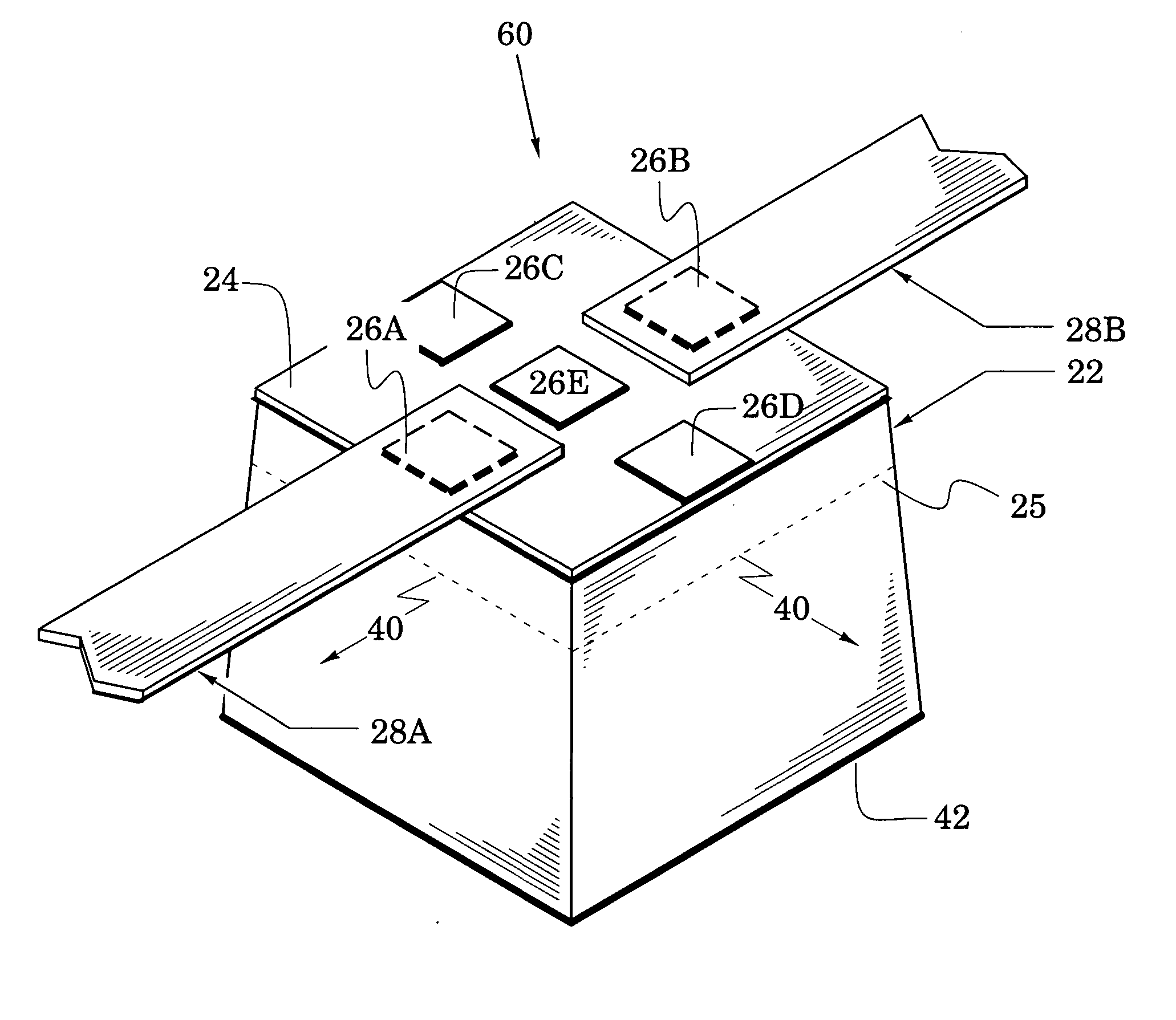
[0019] The embodiment 60 may find utility in various light applications such as one in which different intensities are desired in a string of LEDs. The resistance between the interconnect members 28A and 28B can be used here and in similar light-emitting structures along the string to vary the current, and thus the intensity, of the LEDs of the string. The spacing of the contacts 26A and 26B facilitates this feature.

[0020] In another feature, a second set of contacts 26C and 26D is provided so that the orientation of the LED 22 in FIGS. 1 and 2 is not critical. This embodiment finds utility in light applications such as one in which LEDs are received into mounting structures. With contacts 28A-28D, each LED can be received in the orientation shown in FIGS. 1 and 2 or in an orientation in which it is rotated 90 degrees. In the latter orientation, the interconnect member 28 could be coupled to contacts 28C and 28D in FIG. 1 and the interconnect members 28A and 28B could be respectivel...

embodiment 80

[0023] When a particular one of the structures 80 is formed with a red LED, the interconnect member 28 would be coupled to the resistive member 24A. If the structure is formed instead with a green LED, the interconnect member would be coupled to the resistive member 24B. The embodiment 80 reduces lighting costs because all LEDs can be fabricated with a standard resistive pattern. Alternatively, the resistive members 24A and 24B may both correspond to one LED color (e.g, red) and their different resistivities and cross sections used to selectively adjust the intensity of the radiation of that color.

[0024] Although the resistive pattern of FIG. 3 provides two resistive members, other patterns may be substituted that provide a greater number of resistive members. For example, a pattern that defines three resistive members could be used with red, yellow and green LEDs.

[0025] Another embodiment is shown in FIG. 4 as the light-emitting structure 100 which includes elements of FIG. 1 with...


PUM


Abstract

Light-emitting structures of reduced size are realized with combinations of light-emitting diodes, resistive and conductive films, and interconnect members. Other embodiments are provided which simplify fabrication and assembly.

Description

BACKGROUND OF THE INVENTION [0001] 1. Field of the Invention [0002] The present invention relates generally to light-emitting diodes. [0003] 2. Description of the Related Art [0004] Various light-emitting structures have been proposed in response to the advantageous features of light-emitting diodes (e.g., low voltage, low heating, low maintenance, color diversity and long life). These structures, however, are generally complex and large because they include a number of elements (e.g., body, lens and large, discrete resistors) so that they are not suitable for a variety of lighting applications that require small, inexpensive light structures. BRIEF SUMMARY OF THE INVENTION [0005] The present invention is directed to light-emitting structures that facilitate size and cost reduction and simplified fabrication and assembly. [0006] The novel features of the invention are set forth with particularity in the appended claims. The invention will be best understood from the following descri...

Claims


Application Information

Patent Timeline
IPC IPC(8): H01L25/16H01L33/44H01L33/48H05B33/00
CPCH01L25/167H01L27/15H01L33/44H01L33/48H01L24/73Y10S362/80H01L2924/3011H01L2224/48091H01L2924/00014H01L2924/12044H01L2924/12041H01L2924/00
Inventor RATCLIFFE, WILLIAM R.
Owner GENERAL LED