Variable attenuation network

a variable attenuation and network technology, applied in the field of electronic circuits, to achieve the effect of multiple resolution levels

Inactive Publication Date: 2005-08-11
STMICROELECTRONICS SRL
View PDF3 Cites 27 Cited by
  • Summary
  • Abstract
  • Description
  • Claims
  • Application Information

AI Technical Summary

Problems solved by technology

With such conventional attenuation networks, it is not possible to continuously vary the attenuation ratio because only N pre-established values are provided, but it can be increased or decreased stepwise by a fixed quantity, thus the attenuation ratio is determined with a certain design resolution.

Method used


Image

  • Variable attenuation network
  • Variable attenuation network
  • Variable attenuation network

Examples


Embodiment Construction

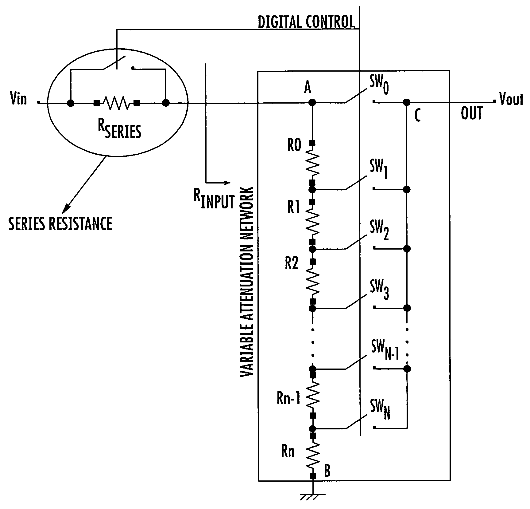
[0011] The variable attenuation network of th invention is obtained by connecting at least a resistor that may be shorted by a switch to a voltage divider and a first embodiment is shown in FIG. 2. By adding one or more resistors of appropriate value in series, upstream or downstream (between the resistor RN and ground) of a voltage divider, or even between the selected tap (node C) and the output OUT of the attenuation network, the resolution of the voltage divider is enhanced without redesigning the voltage divider network in a simple and relatively inexpensive manner.

[0012] The embodiment of FIG. 2 will now be analyzed in detail and a skilled artisan will immediately recognize that the same considerations hold, with the necessary changes, even if the resistor RSERIES is connected between the node B and ground or between the node C and the output node OUT of the attenuation network of this invention. Referring to FIG. 2, assume that only the switch SWX is closed while all other s...


PUM


Abstract

A variable attenuation network of an input voltage on an input node produces an attenuated voltage on an output node of the network, and includes a voltage divider with multiple-taps that are selectable for producing the attenuated voltage from a voltage applied on the terminals of the voltage divider. The attenuation network produces an output voltage with an attenuation ratio that is determined with at least twice the resolution of the voltage divider, because it includes at least one resistor that may be shorted by a low impedance by-pass line controlled by a switch and alternatively connected between the selected intermediate tap or any one of the two terminals of the voltage divider and the output node of the variable attenuation network, the input node of the attenuation network or a common ground node, respectively. By using more than one shortable resistor, multiple levels of resolution may be obtained.

Description

FIELD OF THE INVENTION [0001] The present invention relates to the field of electronic circuits and more particularly, to a high resolution variable attenuation network. BACKGROUND OF THE INVENTION [0002] In signal processing it is often required to vary the gain with which signals are amplified. Commonly, the signals to be amplified are input to a high gain amplifier, the gain of which may generally be larger than desired, thus the output of the high gain amplifier is attenuated to obtain a signal of desired amplitude. [0003] Variable attenuation networks may include resistive voltage dividers, as depicted in FIG. 1a, or of resistive ladders, as that of FIG. 1b, with multiple selectable taps for obtaining a certain attenuation. The attenuation ratio is set by closing only one of the N switches, controlled by a dedicated control circuit (not shown in the FIGURE) through the command DIGITAL CONTROL. With such conventional attenuation networks, it is not possible to continuously vary ...

Claims


Application Information

Patent Timeline
Patent Type & Authority Applications(United States)
IPC IPC(8): H03H7/25H03L5/00
CPCH03H7/25
Inventor CALO', PIETRO ANTONIO PAOLOSIRITO-OLIVIER, PHILIPPE
Owner STMICROELECTRONICS SRL
Why Eureka
Try Eureka