Multi-beam laser rangefinder

a laser rangefinder and beam technology, applied in the field of laser rangefinders, can solve the problems of pressure and radar driven measurement systems used for airborne platform guidance that are generally inaccurate, and cannot be used for calculating the roll or pitch of airborne platform

Inactive Publication Date: 2005-08-11
THE STATE OF ISRAEL MINIST OF AGRI & RURAL DEV AGRI RES ORG ARO VOLCANI CENT
View PDF4 Cites 16 Cited by
  • Summary
  • Abstract
  • Description
  • Claims
  • Application Information

AI Technical Summary

Problems solved by technology

By way of introduction, pressure and radar driven measurement systems used for airborne platform guidance are generally inaccurate, especially at low altitudes where higher precision is needed.
In addition, the altitude calculation cannot be used to calculate roll or pitch of airborne platform 14 relative to the ground nor the time-to-hit the ground by airborne platform 14 for automatic landing purposes.

Method used


Image

  • Multi-beam laser rangefinder
  • Multi-beam laser rangefinder
  • Multi-beam laser rangefinder

Examples


Embodiment Construction

[0043] The present invention is a multi-beam rangefinder system and method of operation thereof.

[0044] The principles and operation of a multi-beam rangefinder system according to the present invention may be better understood with reference to the drawings and the accompanying description.

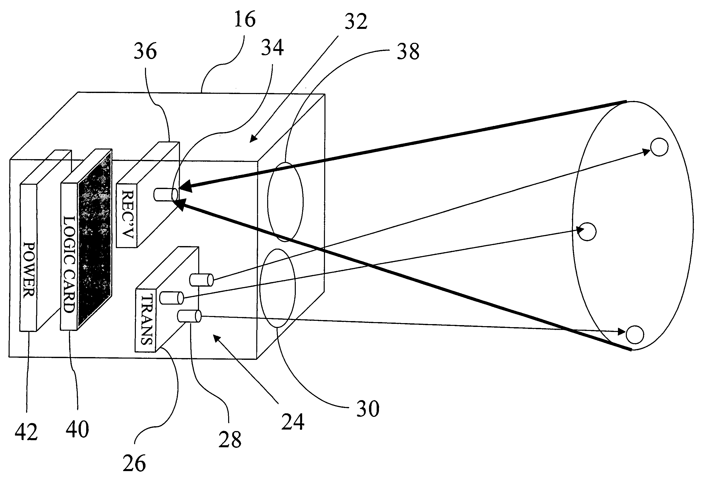
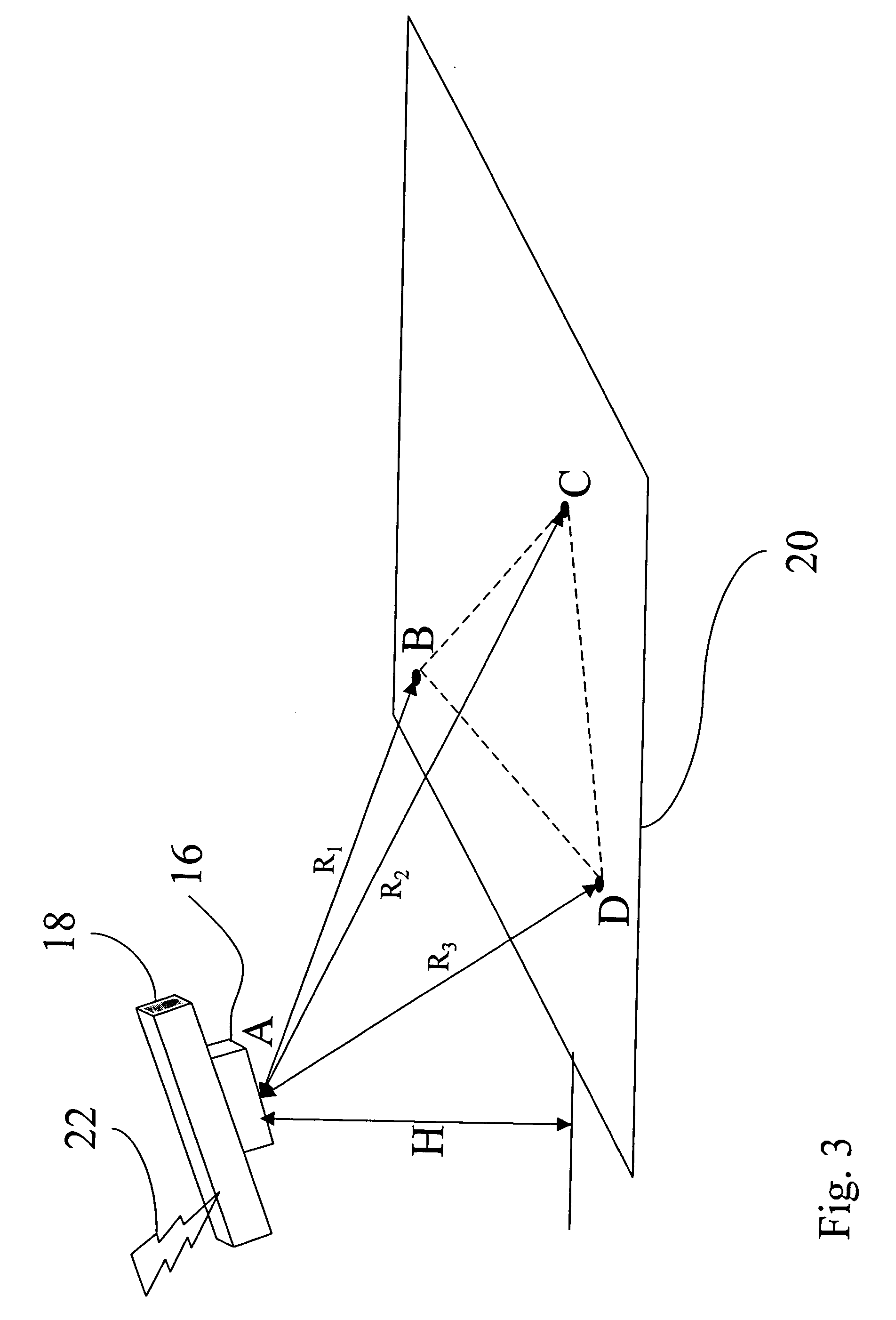
[0045] Reference is now made to FIG. 3, which is a schematic view of a multi-beam laser rangefinder system 16 performing measurements that is constructed and operable in accordance with a preferred embodiment of the invention. Multi-beam laser rangefinder system 16 is configured for estimating a range-derived value of an airborne platform 18 relative to the ground 20. Multi-beam laser rangefinder system 16 performs time of flight calculations on directed laser pulses. These time of flights are typically, but not always, used to calculate the distance from the source of the laser pulses to the target of the laser pulses. Therefore, a range-derived value is defined herein as, any value that is det...


PUM


Abstract

A multi-beam rangefinder system for estimating a range-derived value of an airborne platform relative to the ground. A planar model approximates the ground. The system includes a transmitter arrangement to produce a number of pulses of electromagnetic radiation directed in three or more non-coplanar directions and a sensor arrangement for sensing the pulses of electromagnetic radiation reflected from the ground. The systems also includes a processor arrangement for processing independent measurement of time of flight of the pulses in each of the three or more non-coplanar directions, in order to estimate the range derived value of the airborne platform relative to the ground.

Description

FIELD AND BACKGROUND OF THE INVENTION [0001] The present invention relates to a laser rangefinder and, in particular, it concerns a multi-beam laser rangefinder. [0002] By way of introduction, pressure and radar driven measurement systems used for airborne platform guidance are generally inaccurate, especially at low altitudes where higher precision is needed. [0003] Laser rangefinders are used to measure distances to near and distant objects by measuring the time taken for laser pulses to travel to and from a target. The direction of the laser beam greatly affects the measurement taken, as will now be explained. Reference is now made to FIG. 1, which is a schematic view of a single-beam rangefinder 10 that is constructed and operable in accordance with the prior art. Single-beam rangefinder 10 is disposed on an airborne platform 14. Due to the orientation of airborne platform 14, the line of sight 12 of single-beam rangefinder 10 is directed to point A on the surface of the ground ...

Claims


Application Information

Patent Timeline
Patent Type & Authority Applications(United States)
IPC IPC(8): G01S17/875G01S13/87G01S13/88G01S13/935G01S17/58G01S17/88G01S17/933
CPCG01S13/874G01S13/882G01S13/94G01S17/933G01S17/875G01S17/88G01S17/58G01S13/935
Inventor IMBER, AMIRGOSHTCHEVSKY, CHRIS
Owner THE STATE OF ISRAEL MINIST OF AGRI & RURAL DEV AGRI RES ORG ARO VOLCANI CENT
Why Eureka
Try Eureka