
Image correction method, image correction apparatus, and image correction program

Inactive Publication Date: 2005-08-11
FUJIFILM CORP +1
View PDF54 Cites 50 Cited by
  • Summary
  • Abstract
  • Description
  • Claims
  • Application Information

AI Technical Summary

Benefits of technology

[0007] In view of the foregoing, it is an object of the present invention to provide an image correction method, an image correction apparatus and an image correction program, which facilitate visual identification of differences in results of image correction caused by differences in correction parameters.
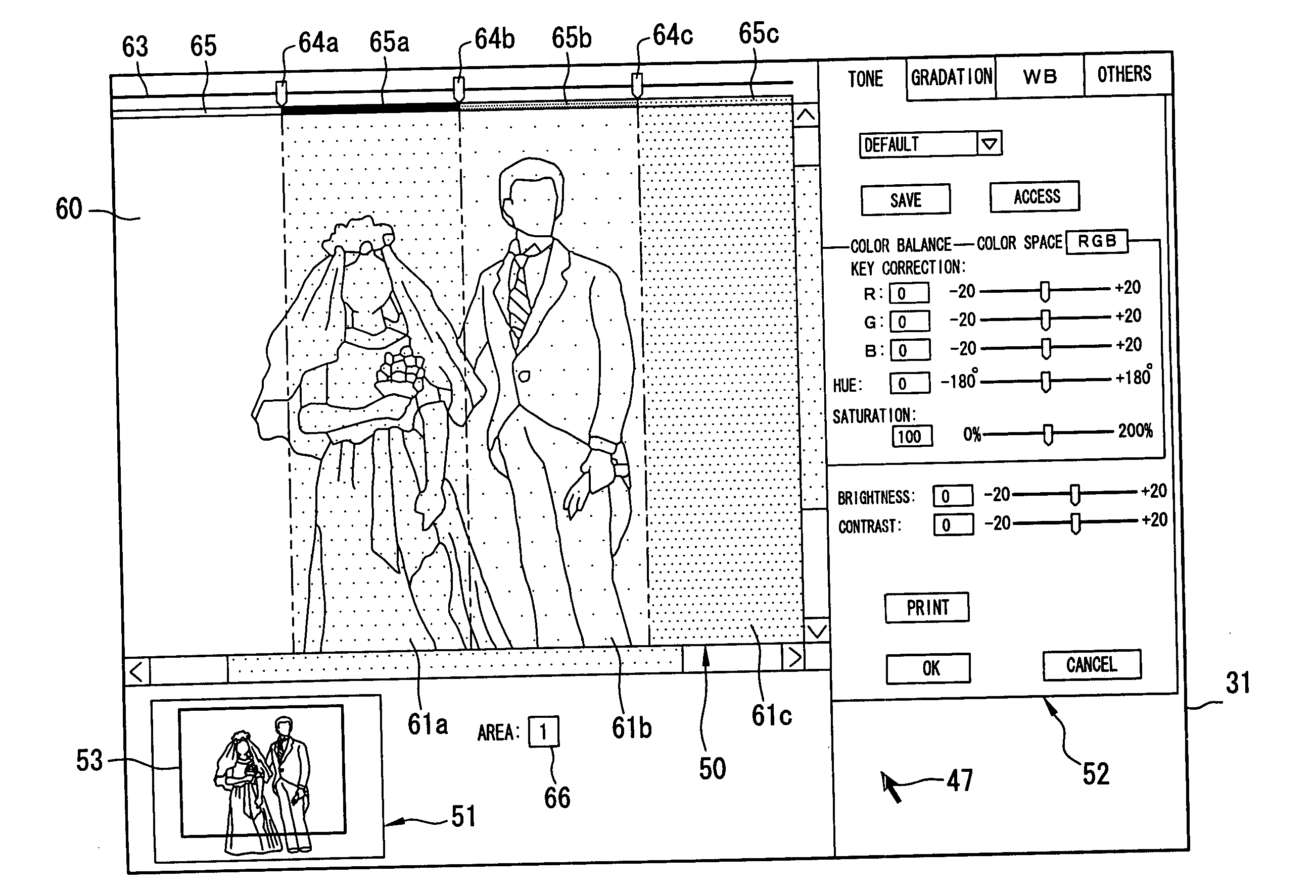
[0011] It is possible to keep an image display range in each partial display area at a constant proportion while changing a position or a size of the target image, which is to be displayed in the image display area. It is also possible to change the position or the size of the target image displayed in the image display area while keeping a position of the boundary of the partial display areas constant with respect to the target image.
[0015] According to the present invention, a single target image, which is formed of each section corrected by different correction parameters, is displayed by dividing the image display area on the monitor into a plurality of the partial display areas, and partially displaying the target image, which is corrected by the individual correction parameters, in each partial display area. Therefore, the differences in the results of the image correction, which are caused by the differences in the correction parameters, can be visually identified with ease. Therefore, the image correction is carried out efficiently.

Problems solved by technology

Therefore, the differences in the results of the image correction are distinguishable if the differences in the correction parameters are significant; however, the differences in the results of the image correction cannot be easily distinguished when the differences in the correction parameters are small, for instance, when making fine adjustments.
Image correction processing cannot be carried out efficiently when the results of the image correction are difficult to distinguish.

Method used


Image

  • Image correction method, image correction apparatus, and image correction program
  • Image correction method, image correction apparatus, and image correction program
  • Image correction method, image correction apparatus, and image correction program

Examples


Embodiment Construction

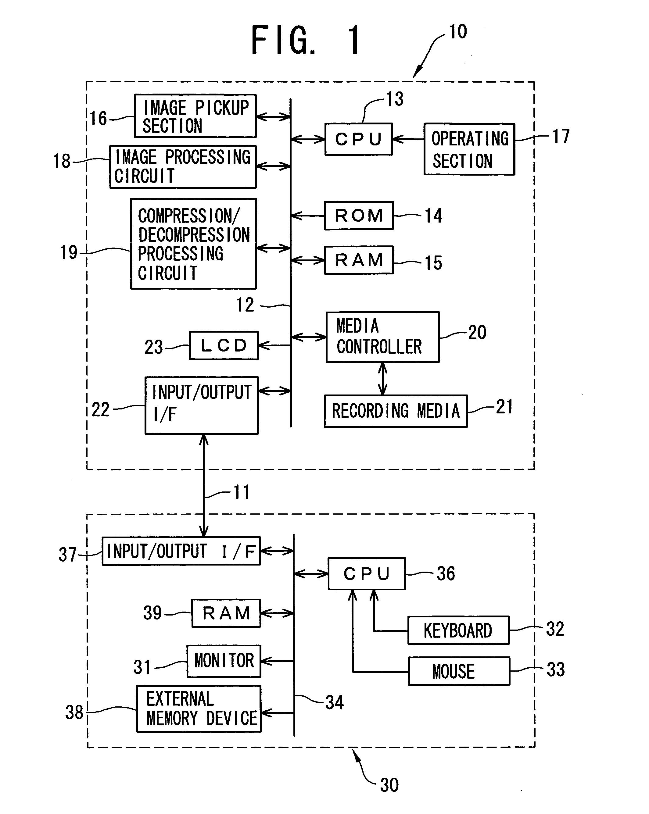
[0031] Commercially available personal computer, in which an image correction program is installed, is used for a personal computer (PC) 30 for image correction. As shown in FIG. 1, a digital camera 10 and the PC 30 for the image correction are connected via a communication cable 11 to transmit and receive camera control data and image data between the digital camera 10 and the PC 30 for the image correction. As for the communication cable 11, for instance, a USB (Universal Serial Bus)-compliant communication cable or an IEEE 1394-compliant communication cable can be used. Wireless communication means can also be used for exchanging data between the digital camera 10 and the PC 30 for the image correction instead of the communication cable 11.

[0032] Each section of the digital camera 10 is interconnected via a data bus 12, and a CPU 13 controls overall operations of the digital camera 10. A program for operating the digital camera 10 is recorded in ROM 14, and is loaded in RAM 15 w...


PUM


Abstract

A main display section is divided into a plurality of display areas (partial display areas). In each display area, image correction is carried out according to individual correction parameters. A target image for image correction is displayed in an image display area as a single image in a state that each section displayed in each display area has been corrected by using different parameters. In response to moving an indicator, which is displayed on an upper side of the main display section, along a slide bar, a size and a position of each display area is changed. An area size display bar, which shows a display range of each display area, is displayed on the upper side of the main display section. When one display area is selected for inputting the correction parameters, a section of the area size display bar, which corresponds to the selected display area, is highlighted.

Description

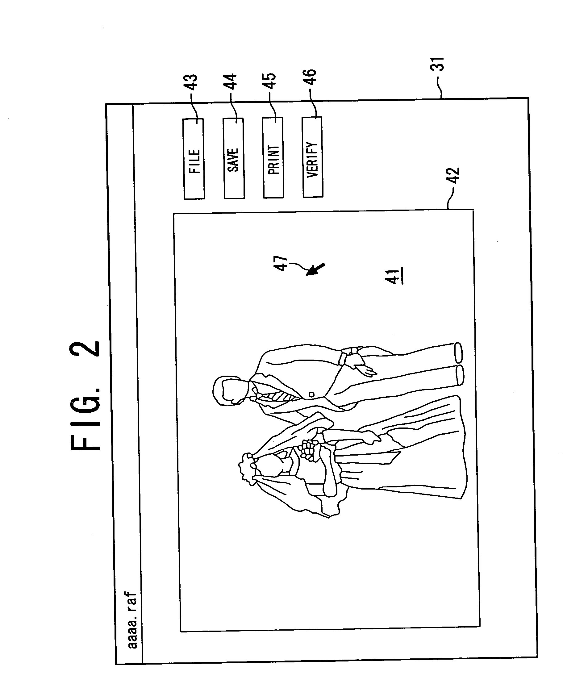
BACKGROUND OF THE INVENTION [0001] 1. Field of the Invention [0002] The present invention relates to a method, an apparatus and a program for correcting images while observing images displayed on a monitor provided in an information processing terminal such as a personal computer. [0003] 2. Background Arts [0004] Digital image quality can be improved by correcting color balance or tone curve of a digital image by using an information processing terminal, such as a personal computer (PC) . For instance, in a digital camera shooting, image data is transmitted from the digital camera to the PC. An operator can obtain an image with excellent finished quality as intended by adjusting various correction parameters while observing an image displayed on a monitor of the PC. Further, it is also possible to apply image correction by the PC while keeping color information in the digital camera by using a digital camera which is able to output initial image data (RAW data) to the PC without app...

Claims


Application Information

Patent Timeline
IPC IPC(8): G06T11/80G06F3/00G06F3/048G06F3/0484G06F3/14G06F17/00G06K15/02H04N1/60H04N1/62
CPCH04N1/622
Inventor KUBO, MASAHIRO
Owner FUJIFILM CORP
Learn More