Image scanning device and its control method

a technology for scanning devices and document images, applied in the direction of picture signal generators, solid-state device signal generators, instruments, etc., can solve the problems of poor color reproducibility of emerald systems, small light-receiving area of each extraction unit, and inability to achieve high color reproducibility. , to achieve the effect of simple arrangement and faithful color reproduction

Inactive Publication Date: 2005-08-11
CANON KK
View PDF14 Cites 32 Cited by
  • Summary
  • Abstract
  • Description
  • Claims
  • Application Information

AI Technical Summary

Benefits of technology

[0009] The present invention has been made in consideration of the above problems, and has as its object to provide a technique which can achieve more faithful color reproduction by a relative simple arrangement.

Problems solved by technology

However, high color reproducibility has not been obtained yet.
Hence, the color reproducibility of an emerald system is prone to be poor.
However, according to the technique of this reference, since data for one pixel is extracted by extraction units of independent colors, the light-receiving area of each extraction unit becomes too small to obtain a sufficient light-receiving amount.
In addition, higher cost is required to manufacture such image sensing element, and it is difficult to apply this method to the image scanning device.

Method used


Image

  • Image scanning device and its control method
  • Image scanning device and its control method
  • Image scanning device and its control method

Examples


first embodiment

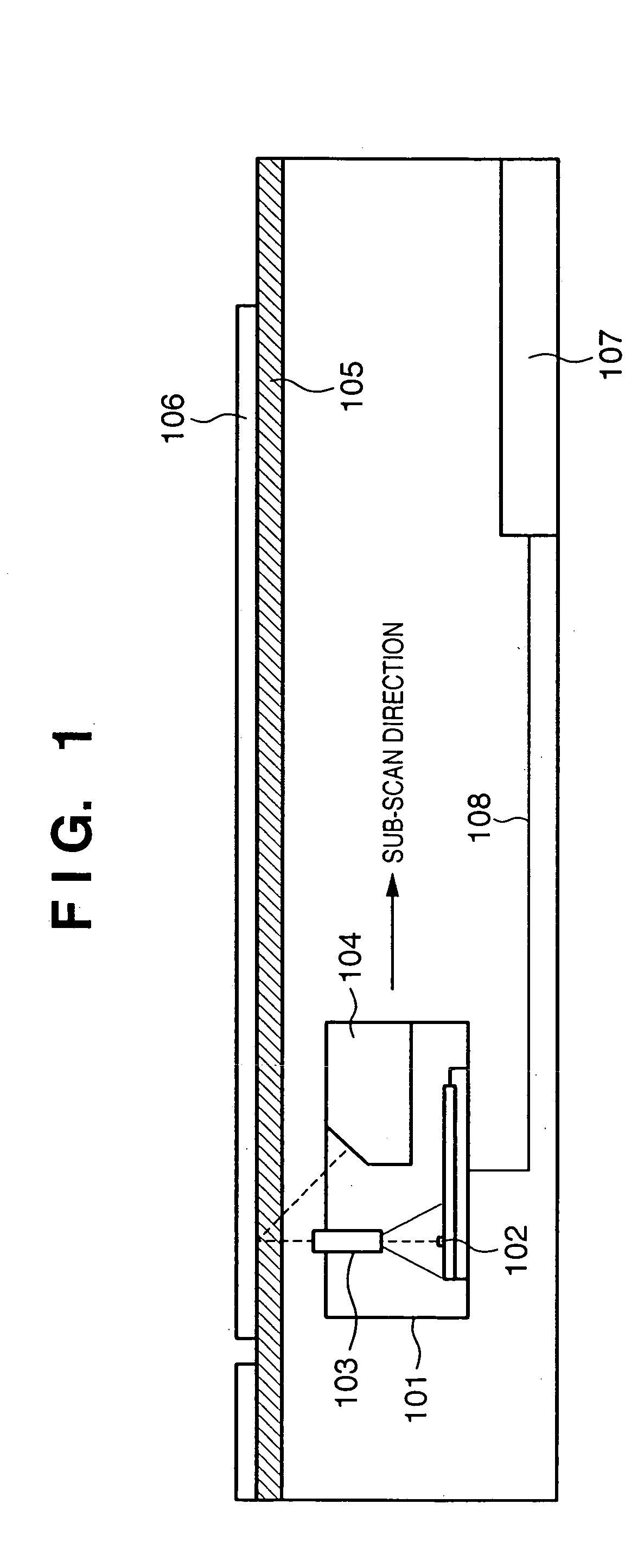
[0036]FIG. 1 is a schematic sectional view of a document scanning device (image scanner) of this embodiment.

[0037] Referring to FIG. 1, reference numeral 101 denotes a contact image sensor unit (to be abbreviated as CIS hereinafter). Reference numeral 104 denotes an optical waveguide light source in which a red LED (R-LED), green LED (G-LED), blue LED (B-LED), and an emerald LED (emerald color will be referred to as E color hereinafter, and the emerald LED will be referred to as E-LED hereinafter) are arranged at the end portion of the waveguide which is elongated in a direction perpendicular to the plane of page (main scan direction), and which guides light emitted by each LED in the main scan direction by internal reflection to linearly irradiate a document 106 to be scanned on a document table glass (platen glass) 105 with that light.

[0038] Light reflected by the document surface is received by a monochrome image sensor 102 via a lens array 103. Light-receiving elements of the ...

second embodiment

[0083] In the first embodiment, the color correction processes in the three-color scan mode and four-color scan mode are executed on the image scanning device side. Alternatively, the scanned R, G, and B or R, G, B, and E component data may be output to the host computer, which may execute the correction processes. When the correction processes are done on the host computer side, that correction function can be added to an image scanner driver which runs on the host computer. As a result, the edit processes that can obtain the effects of the above embodiment can be made without modifying a normal image processing application.

[0084] An implementation example of the color correction processes by a scanner driver on the PC 300 side will be explained hereinafter as the second embodiment.

[0085] The structure of the image scanning device is the same as that shown in FIG. 7. However, when the 32-bit multi-valued mode is set, the image scanning device directly outputs 8-bit data of R, G, ...

third embodiment

[0107] A case will be explained below wherein the transmitting document illumination unit 210 (see FIG. 7) is used. The transmitting document illumination unit 210 includes four LEDs, i.e., R, G, B, and E LEDs if it is applied to the first embodiment.

[0108] Nowadays, a four-layered silver halide film to which a color sensitive layer sensitive to emerald is added in addition to red, green, and blue color sensitive layers is commercially available, as disclosed in Japanese Patent Laid-Open No. 2003-84402. Since the transmitting document illumination unit 210 of this embodiment includes four, R, G, B, and E light sources (LEDs) as in the above description, it scans a transmitting document of such four-layered silver halide film, thus obtaining a scanned image with higher color reproducibility.

[0109]FIG. 11 is a sectional view when the transmitting document illumination unit 210 is connected to the interface 208 of this device via a cable 230. In FIG. 11, reference numeral 220 denotes...


PUM


Abstract

This invention provides a technique which allows more faithful color reproduction by a relative simple arrangement. To this end, according to this invention, by time-divisionally driving R, G, B, and E LEDs respectively having dominant emission wavelengths of 630 nm, 525 nm, 470 nm, and 500 nm, a common monochrome line image sensor (102) scans a document image. Scanned image data of respective color components undergo correction equivalent to that attained by shifting the barycentric positions of respective wavelength distributions so as to become closer to the CIE-RGB sensitivity distributions.

Description

FIELD OF THE INVENTION [0001] The present invention relates to a technique for scanning a document image, and outputting it as a digital image signal. BACKGROUND OF THE INVENTION [0002] Normally, an image scanning device represented by a color image scanner and the like has light sources (e.g., LEDs) with emission wavelength characteristics of red (R), green (G), and blue (B), and scans information from a document using a common monochrome line image sensor while switching the ON / OFF states of them, and obtains two-dimensional image information while moving the monochrome line image sensor or document in a direction perpendicular to the arrangement direction of detection elements of the monochrome line image sensor (normally called a sub-scan direction) (e.g., Japanese Patent Laid-Open No. 2003-315931). [0003] The luminous spectrum characteristics of the LEDs of respective colors as R, G, and B light sources used in the image scanning device are approximately as shown in FIG. 3. [00...

Claims


Application Information

Patent Timeline
Patent Type & Authority Applications(United States)
IPC IPC(8): H04N1/028H04N1/04H04N1/40H04N1/48H04N9/04
CPCH04N9/045H04N1/484
Inventor FUKAWA, KIMIHIKO
Owner CANON KK
Why Eureka
Try Eureka