Belt driving apparatus and image forming apparatus that uses the belt driving apparatus
- Summary
- Abstract
- Description
- Claims
- Application Information
AI Technical Summary
Benefits of technology
Problems solved by technology
Method used
Image

Examples
first embodiment
{Construction}
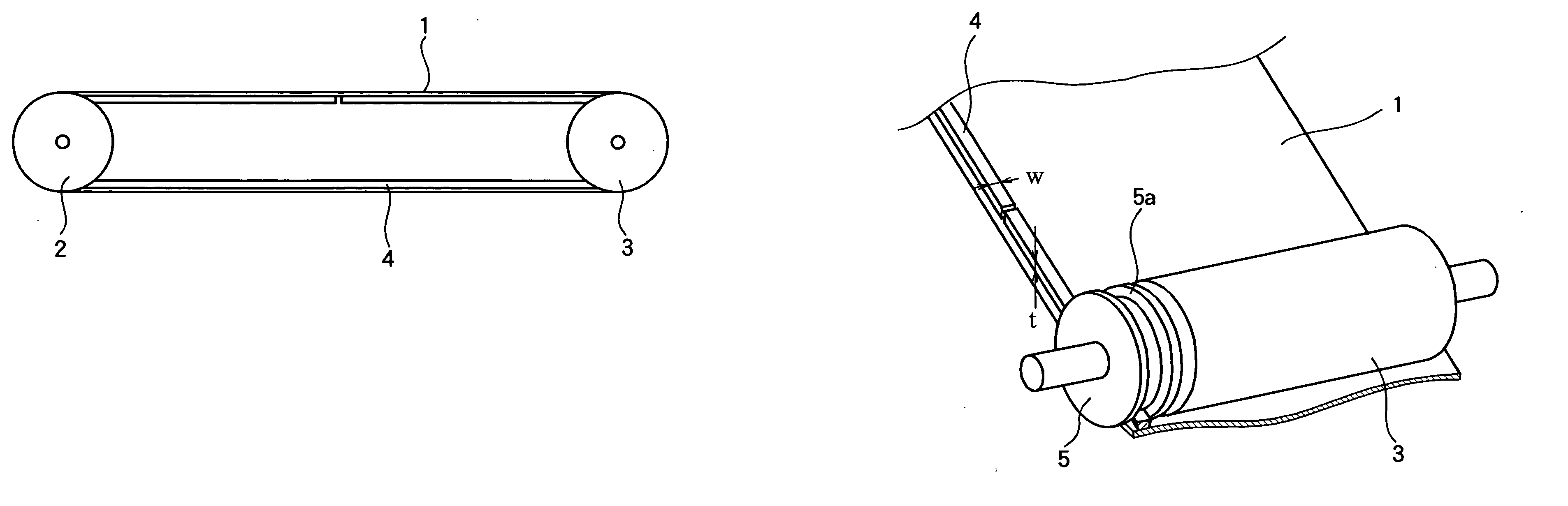
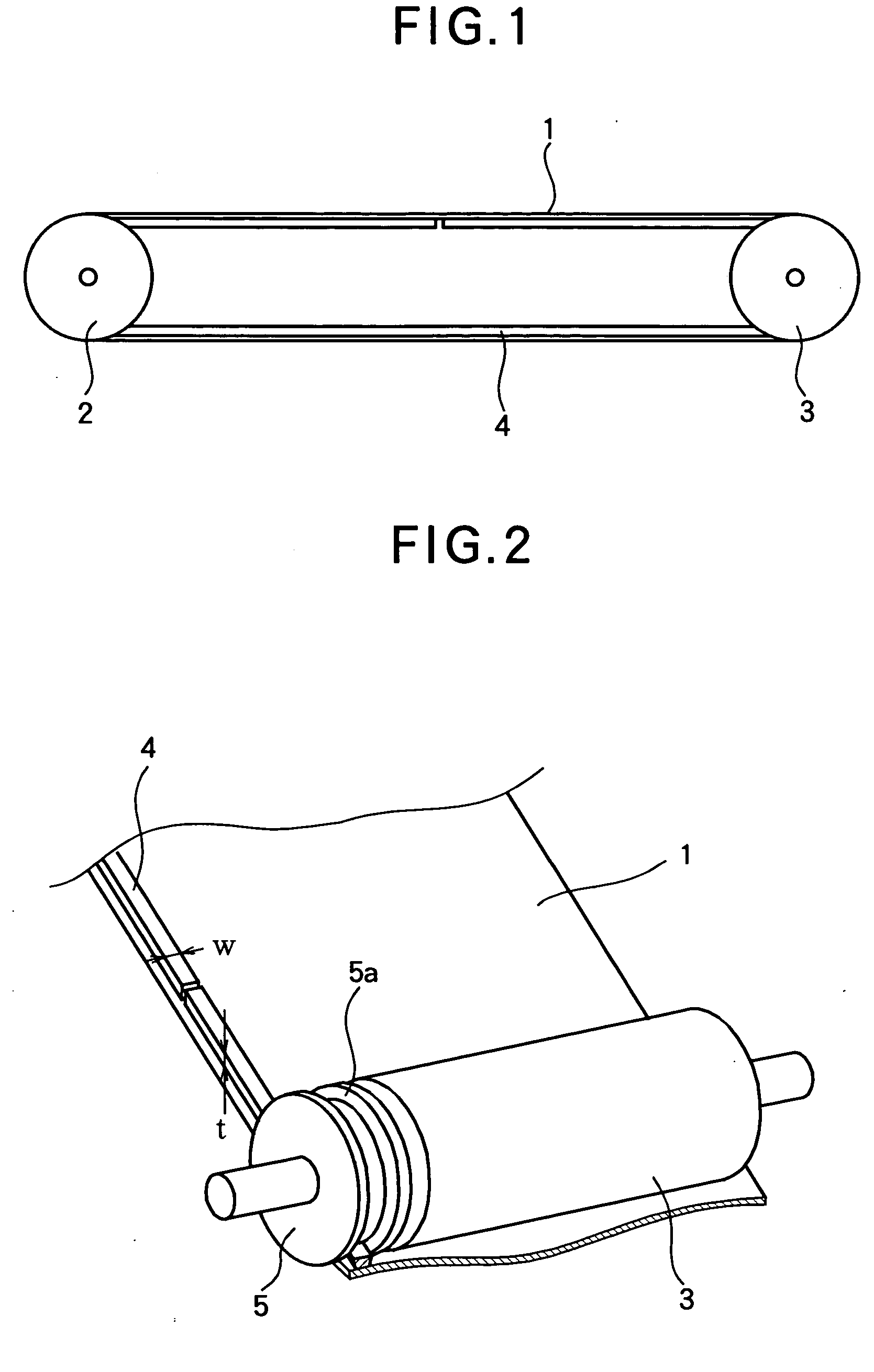
[0021]FIG. 1 is a schematic side view illustrating a transfer belt according to a first embodiment.
[0022]FIG. 2 is a perspective view illustrating an outline of the belt according to the first embodiment, the belt being shown in a cut away view.
[0023] Referring to FIG. 1 and FIG. 2, the transfer belt 1 is entrained about a drive roller 2 and a driven roller 3 under a predetermined tension, so that when the drive roller 2 rotates, the driven roller 3 rotates and a transfer belt 1 runs. By using SUPER-X available from CEMEDINE, a belt guide 4 is bonded to one widthwise end portion of the transfer belt 1 and extends along the loop-like inner surface of the transfer belt 1. The belt guide 4 has a width W of 5 mm and a thickness t of 1 mm. A pulley 5 is concentric with the driven roller 3 and is mounted near the driven roller 3 such that the pulley 5 is rotatable independently of the driven roller 3. The pulley 5 guides the belt guide 4, while also being limited in its a...
second embodiment
[0038]FIG. 4 is a cross-sectional view illustrating the general configuration of a belt guide 4 according to a second embodiment. The belt guide 4 has a laminated structure of a layer 4a and a layer 4b. The layer 4a is formed of urethane rubber that shows good resistance to fatigue and good resistance to wear. The layer 4b includes, for example, urethane rubber on which a reinforce material such as polyethylene terephthalate (PET) and polypropylene is laminated. The material for the belt guide 4 is not limited to these and the number of layers is not limited to two.
[0039] The thus formed belt guide has a dissipation factor of tan δ≧0.05 and a storage modulus of E′≧8.0×10⁶ (Pa). These physical quantities are obtained at a furnace temperature of 50±0.5° C. and a resonance frequency of 1 Hz±10%. The measurement was made according to JISK7244-4 (Determination of Dynamic Mechanical Properties of plastics, Part 4: Tensile Vibration—Non-resonance Method). The rest of the configuration is ...
third embodiment
[0044] The operation of a third embodiment is the same as that in the first embodiment and therefore the description thereof is omitted. The third embodiment will be described with reference to Table 3. By using the same stamping press used for stamping the belt guide, the same sheet of material as guide material #1 was stamped out to form a total of six guide materials #1. Each of the six guide materials #1 were bonded to the transfer belt 1 to prepare six test belts B1-B6. Likewise, the same sheet of material as guide material #2 was stamped out to form a total of six guide materials #2, and each of the six guide materials #2 was bonded to the transfer belt 1 to prepare six test belts N1-N6. A 180-degree peel strength test was performed for six test belts B1-B6 that use the six guide materials #1 and six test belts N1-N6 that use the six guide materials #2. The peel rate was 300 mm / min. The materials were bonded using Super-X available from CEMEDINE. Table 3 lists the test results...
PUM
 Abstract
Description
Claims
Application Information
 - Generate Ideas
- Intellectual Property
- Life Sciences
- Materials
- Tech Scout
- Unparalleled Data Quality
- Higher Quality Content
- 60% Fewer Hallucinations
Browse by: Latest US Patents, China's latest patents, Technical Efficacy Thesaurus, Application Domain, Technology Topic, Popular Technical Reports.
© 2025 PatSnap. All rights reserved.Legal|Privacy policy|Modern Slavery Act Transparency Statement|Sitemap|About US| Contact US: help@patsnap.com