
Infusion pump for syringes

Active Publication Date: 2005-08-11
STAMPI INDA DOLCIARIA AFFINI MILANO
View PDF11 Cites 26 Cited by
  • Summary
  • Abstract
  • Description
  • Claims
  • Application Information

AI Technical Summary

Benefits of technology

[0013] The aim of the present invention is to eliminate the above-mentioned drawbacks of known pumps, by providing an infusion pump for syringes that allows to mix the components of a fluid to be infused uniformly and constantly, to reduce labor use and costs, to contain the time required, and to limit the errors in performing mixing.
[0014] Another object of the present invention is to provide a pump that can be used easily to mix and infuse fluids that contain air or gas microbubbles uniformly, precisely and constantly and allows to reduce the waste of material.
[0016] Within this aim, another object of the present invention is to provide an infusion pump that is simple, relatively easy to provide in practice, safe in use, effective in operation, and has a relatively low cost.

Problems solved by technology

These known types of pump are not free from drawbacks, including the fact that if the fluid to be infused is constituted by a plurality of components they do not allow to mix them adequately as required.
Currently, mixing is performed manually by health operators, who shake the syringe in which the components of the fluid have been introduced, with consequent disadvantageous labor costs and long execution times and producing a homogenization that is imperfect and inconstant since it depends on the experience and dexterity of the operators.
Another drawback of known pumps is that they practically cannot be used to infuse fluids that contain microbubbles of air or gas, such as for example the contrast media used in imaging diagnostic methods, such as in particular echocontrast imaging.
Currently, therefore, the mixing and infusion of these fluids that contain microbubbles of air or gas, as well as the immediate successive infusion of a physiological solution, are entirely manual, and this accordingly entails a further disadvantageous increase in labor costs and in execution times as well as inevitable and unpredictable inaccuracies and errors in execution due to the experience and dexterity of the operators.
Moreover, it should be noted that the contrast media of this type have high intrinsic costs, and therefore their incorrect mixing and / or their incorrect infusion, such as to compromise for example the quality of the resulting sonogram and prevent correct diagnosis, entail a waste of material that is disadvantageously onerous.

Method used


Image

  • Infusion pump for syringes
  • Infusion pump for syringes
  • Infusion pump for syringes

Examples


Embodiment Construction

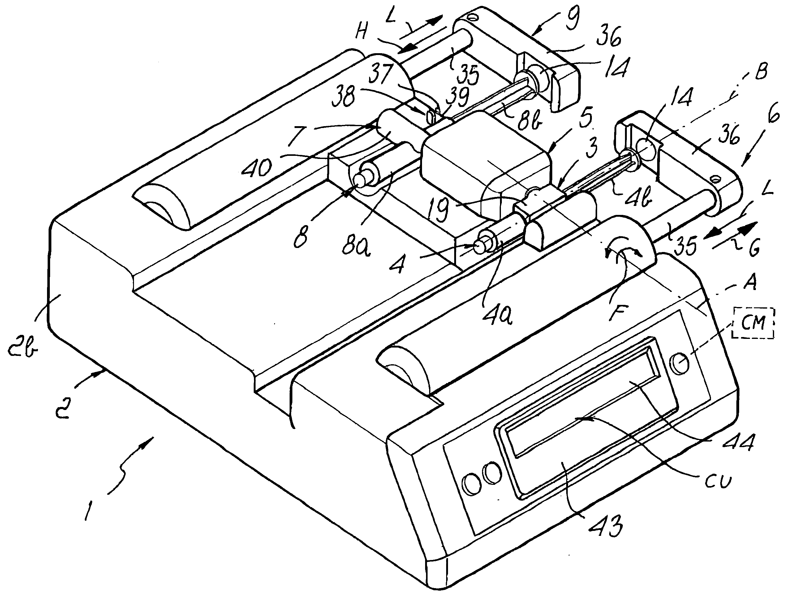
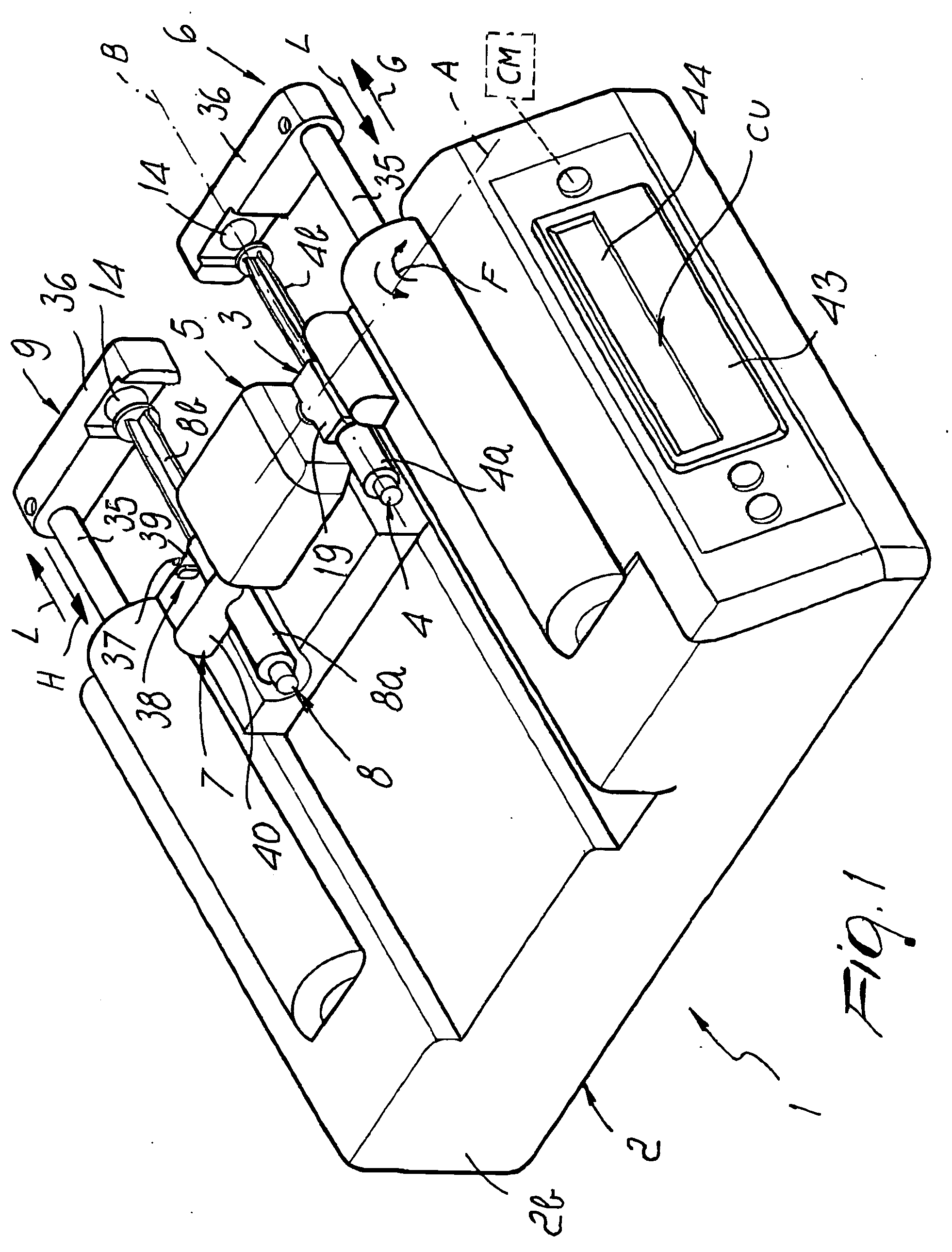
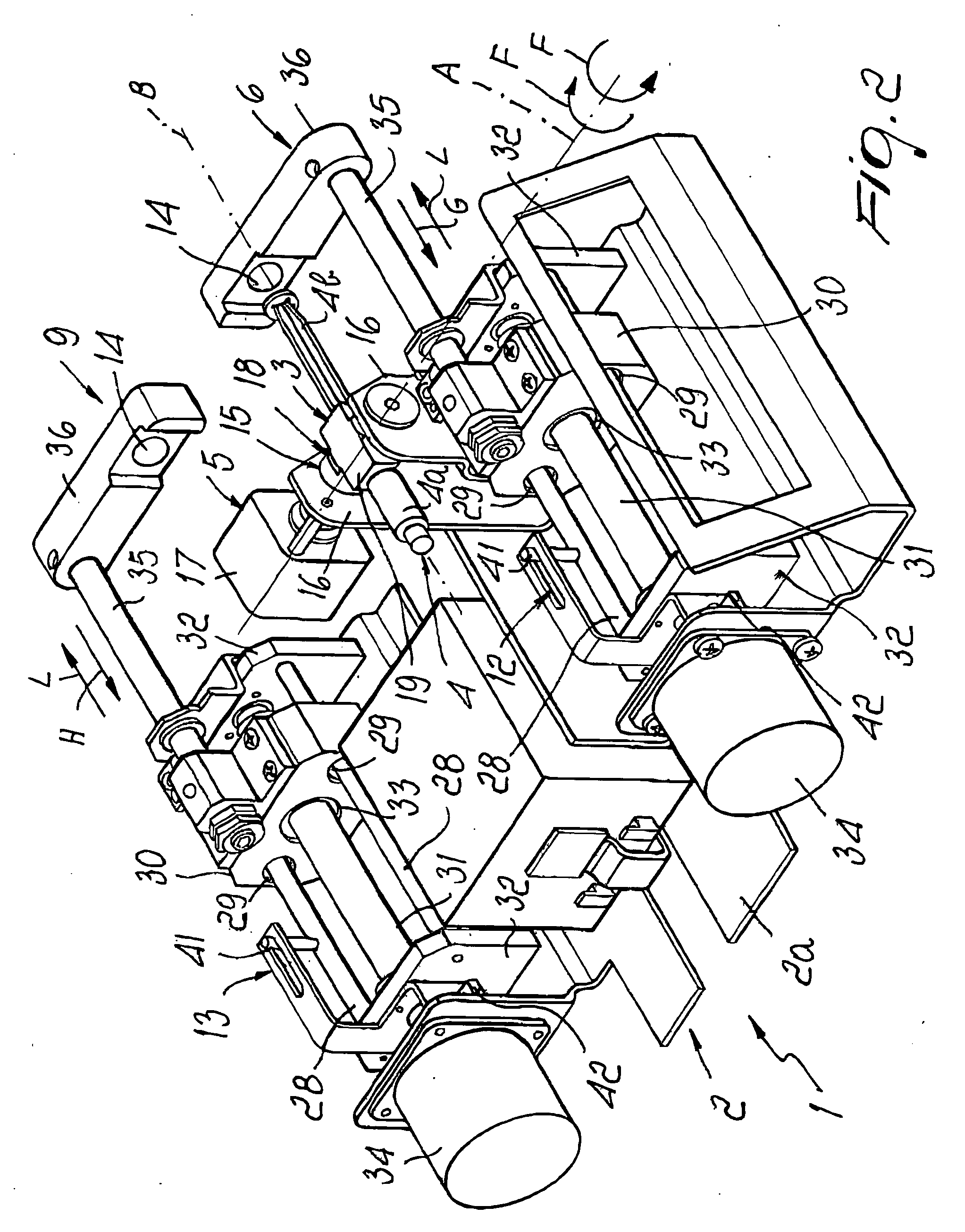
[0025] With reference to the figures, the reference numeral 1 generally designates an infusion pump for syringes.

[0026] The pump 1 comprises a supporting structure 2, which is divided into a base 2a and a housing 2b, means 3 for supporting a syringe 4, of the type constituted by a cylindrical body 4a inside which a plunger 4b slides, which can be rigidly associated with the syringe 4 and can be detachably associated with the supporting structure 2 so as to rotate alternately about a first axis A that is substantially perpendicular to a second longitudinal axis B of the syringe 4.

[0027] The syringe 4, rigidly coupled to the support means 3, is therefore alternately rotated about the axis A with a so-called oscillating or rocking motion.

[0028] Further, the pump 1 comprises first actuation means 5 of the automated type, for actuating the alternating rotation of the support or supporting means 3 and therefore of the syringe 4 that is rigidly coupled thereto; said first actuation mean...


PUM


Abstract

An infusion pump for syringes, comprising a supporting structure, a support for a syringe, which can be rigidly associated with the syringe and can be associated with the supporting structure so that they can rotate alternately about an axis that is substantially perpendicular to the longitudinal axis of the syringe, and a first actuation for actuating the alternating rotation and a second actuation for actuating the sliding of the plunger of the syringe, which cooperate functionally with the first actuation.

Description

[0001] The present invention relates to an infusion pump for syringes. BACKGROUND OF THE INVENTION [0002] Infusion pumps for syringes, used in the therapeutic field for the controlled and automated infusion of drugs, are known. [0003] Known pumps are substantially constituted by a supporting frame, with which means for locking the cylindrical body of a syringe and means of the linear automated type for actuating the sliding of the plunger of the syringe are associated. [0004] An electronic circuit controls and actuates the actuation means in order to dispense the drug contained in the syringe according to an infusion program (time, flow-rate, speed et cetera) that can be set from the outside by a health operator by means of a keypad and a display. [0005] These known types of pump are not free from drawbacks, including the fact that if the fluid to be infused is constituted by a plurality of components they do not allow to mix them adequately as required. [0006] Currently, mixing is ...

Claims


Application Information

Patent Timeline
IPC IPC(8): A61M5/14A61M5/145B01F9/00B01F11/00B01F13/00
CPCA61M5/1407A61M5/1456A61M2205/14B01F13/0023B01F11/0017B01F11/0097B01F13/002A61M2205/3331B01F31/23B01F31/70B01F33/50112B01F33/5011
Inventor AZZOLINI, GRAZIANO
Owner STAMPI INDA DOLCIARIA AFFINI MILANO
Learn More