
Method and apparatus for forming a pattern, device and electronic apparatus

a technology of pattern and electronic apparatus, applied in the direction of compasses, rotary piston liquid engine, testing/calibration of speed/acceleration/shock measurement devices, etc., can solve the problems of high equipment cost and difficulty in improving the landing accuracy of liquid materials, and achieve the effect of improving the landing position of liquid drops from the ejection head

Active Publication Date: 2005-08-11
TOKYO ELECTRON LTD
View PDF10 Cites 67 Cited by
  • Summary
  • Abstract
  • Description
  • Claims
  • Application Information

AI Technical Summary

Benefits of technology

[0008] The present invention was conceived in view of the above described circumstances, and it is an object thereof to provide an apparatus and the like that enable the accuracy of landing positions of liquid drops from an ejection head to be improved by correcting the relative positions between the ejection head and the substrate in each location even when the accuracy of the landing position of the liquid material is different in each location on the substrate.
[0010] Moreover, in the method according to the first aspect of the present invention, the ejection head may include a plurality of ejection heads that are formed integrally, and the steps of detecting an amount of a displacement, determining a relative positional error, determining a correction value, and sequentially changing a relative position of the substrate and the ejection head may be carried out for each of the plurality of ejection heads. According to this aspect, even if relative positional displacement is present between the substrate and the ejection heads, or if the drive shaft that moves the ejection head relatively to the substrate is bent or the like, and if each of the plurality of ejection heads has an assembly error when they are integrated together, because the relative positions of the ejection heads and the substrate are adjusted (i.e., corrected) in sequence for each position of the substrate such that the droplets land on the target positions, it is possible to accurately form a predetermined pattern on the substrate.

Problems solved by technology

However, in the aforementioned technology, a dedicated apparatus is required in order to assemble the ejection heads with a high degree of accuracy, and consequently the problem arises that equipment costs are high.
Moreover, if there is displacement in the relative position of the substrate and the ejection head, or if some errors is caused between each ejection head during assembly when a plurality of ejection heads are formed integrally, or if the drive shaft that moves the ejection head and the substrate relative to each other is deflected, then the problem arises that it is difficult to improve the landing accuracy of the liquid material.

Method used


Image

  • Method and apparatus for forming a pattern, device and electronic apparatus
  • Method and apparatus for forming a pattern, device and electronic apparatus
  • Method and apparatus for forming a pattern, device and electronic apparatus

Examples


Embodiment Construction

[0032] Embodiments of the method and apparatus for forming a pattern, device, and electronic apparatus of the present invention will now be described with reference made to the drawings.

[0033] The pattern forming apparatus of the present invention will now be described with reference made to the drawings.

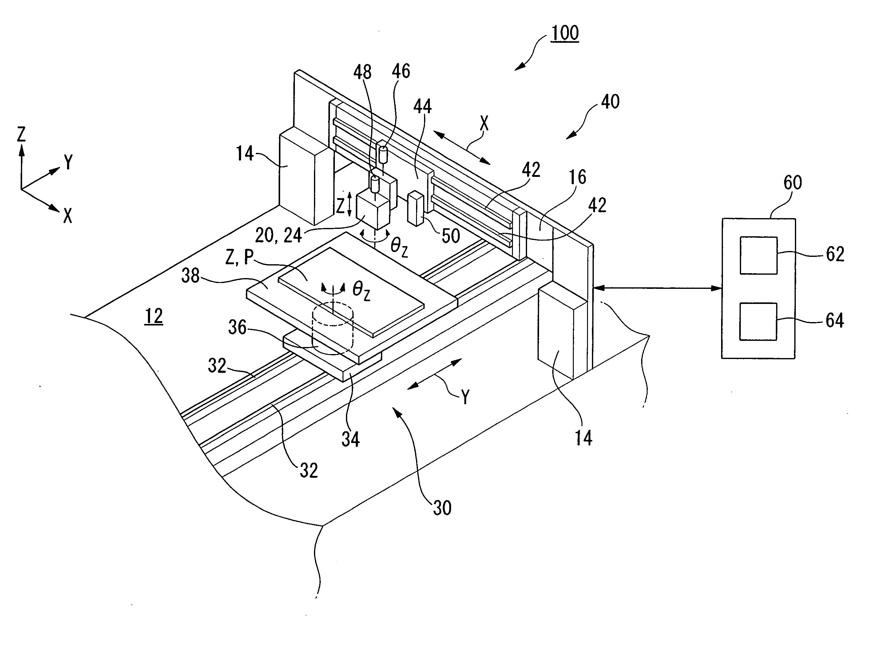
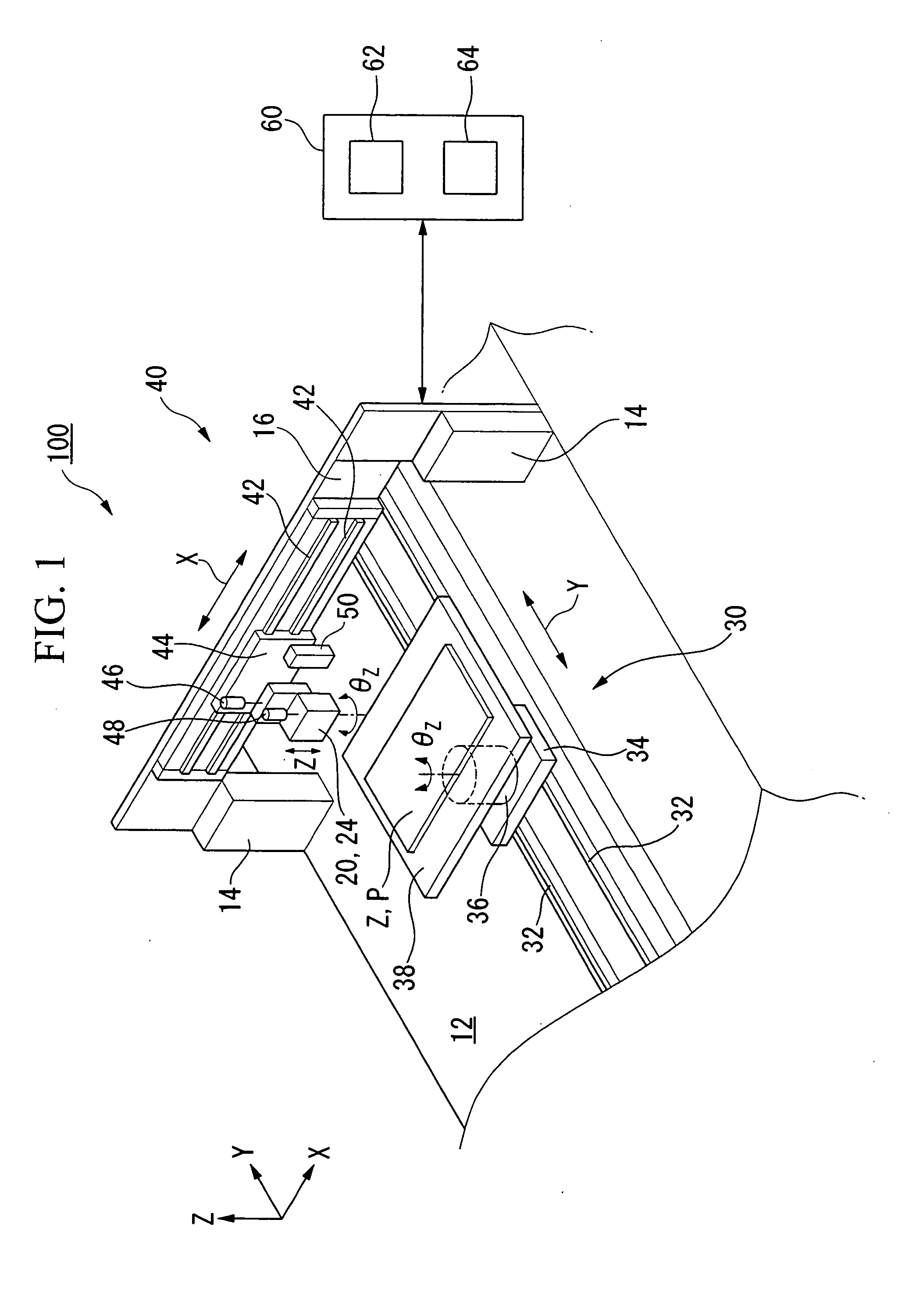
[0034]FIG. 1 is a perspective view showing the pattern forming apparatus 100 of the present invention.

[0035] As shown in FIG. 1, the pattern forming apparatus 100 is a liquid drop ejection apparatus (i.e., an inkjet apparatus) that is capable of supplying a liquid material onto a substrate P or a reference plate Z in a predetermined pattern, and is provided with a base 12 that is arranged horizontally, a stage 38 that is provided on the base 12 and supports a substrate P or reference plate Z, a first shifting apparatus 30 that is placed between the base 12 and the stage 38 and movably supports the stage 38, an ejection head unit 20 that is capable of ejecting (i.e., dripping) pre...


PUM

PropertyMeasurementUnit
Erroraaaaaaaaaa
Displacementaaaaaaaaaa

Abstract

A method for forming a pattern on a substrate, including the steps of: ejecting liquid drops from an ejection head having nozzles onto a reference plate on which a plurality of target positions are defined, the target positions being arranged in at least one row; detecting an amount of a displacement between the target positions and the positions at which the liquid drops have actually landed; determining a relative positional error relative to the ejection head for each of the at least one row of the target positions based on the amount of the displacement; determining a correction value for each of the at least one row based on the relative positional error; and sequentially changing a relative position of the substrate and the ejection head based on the corrections values when the liquid drops are being ejected onto the substrate.

Description

BACKGROUND OF THE INVENTION [0001] 1. Field of the Invention [0002] The present invention relates to a method and apparatus that form a pattern by ejecting liquid drops from an ejection head onto predetermined positions on a substrate. [0003] Priority is claimed on Japanese Patent Application No. 2004-7904, filed Jan. 15, 2004 the contents of which are incorporated herein by reference. [0004] 2. Description of Related Art [0005] Manufacturing methods that employ a liquid drop ejection technique have attracted attention as methods for manufacturing devices having fine wiring patterns, such as semiconductor integrated circuits, and as methods for manufacturing liquid crystal displays or organic electroluminescence (EL) elements. In these manufacturing technologies, a material layer is formed (i.e., painted) on a substrate by ejecting a liquid material that contains a material used to form a pattern from an ejection head (i.e., an inkjet type head) onto a pattern forming screen so as t...

Claims


Application Information

Patent Timeline
IPC IPC(8): B05C5/00H04R9/02B05C11/00B05D3/00B05D7/00B29C65/52B41J2/01G06F11/30H01L21/027H01L51/50H04R1/06H04R9/06H04R31/00H05B33/10H05B33/14
CPCB41J29/393B41J2202/09H04R1/06H04R2400/11H04R31/006H04R2201/34H04R9/06F04C29/028F04C18/356F04C2240/40F04C2210/26
Inventor NAGAE, NOBUAKI
Owner TOKYO ELECTRON LTD
Learn More