Metal cutting circular saw with integral sight window

a circular saw and metal cutting technology, applied in the field of circular saws, can solve the problems of not being able to directly the positioning of the blade remains a problem, and the inability to monitor the blade travel, so as to control and minimize the ejection of chips, the effect of minimizing the light reflected into the eyes

Inactive Publication Date: 2005-08-18
BLACK & DECKER
View PDF30 Cites 5 Cited by
  • Summary
  • Abstract
  • Description
  • Claims
  • Application Information

AI Technical Summary

Benefits of technology

[0006] The position of the viewing window and the saw guard must also count for the chips that are generated as the saw cuts through the work piece. This problem is particularly relevant when the circular saw is used for cutting metal. Thus, there is also a need in the art for metal cutting circular saws to be equipped to protect the user from chips and debris while cutting metal materials. Accordingly, it is an object of the present invention to provide a window assembly in the upper guard of a circular saw in a position so as to minimize any light reflected into the eyes of the person using the saw.
[0007] It is another object of the present invention to provide a guard design which controls and minimizes the ejection of chips along with a saw shoe, and lower guard design which is optimized for the same purpose. It is a further object of the present invention to provide an upper guard which is made of strong material and which provides plenty of light to be passed therethrough to illuminate the cutting line and blade interface area.

Problems solved by technology

One of the problems associated with the use of a handheld circular saw is properly aligning the saw so that the desired cut is achieved.
The problem arises when the user of the handheld circular saw attempts to align the blade with the line on the material.
The problem continues as the user attempts to keep the blade tracking on the desired cut line.
While the provision of such a guide slot does aid the user in proper saw alignment, problems still exist.
Because the blade is covered by a saw guard, the user cannot see the blade as it exits the material and therefore cannot directly monitor the travel of the blade.
While this viewing window solves the problems to some degree, its positioning remains a problem.
If the viewing window is not properly positioned, the user will be unable to see the blade exiting the material due to the reflection of light by the transparent section of the viewing window.
If the user repositions himself / herself relative to the saw, the resulting position may be an uncomfortable or unsafe one from which to operate the saw.
Further, the trial and error necessary to find a proper position of saw, user and light source waste the user's time.
This problem is particularly relevant when the circular saw is used for cutting metal.

Method used


Image

  • Metal cutting circular saw with integral sight window
  • Metal cutting circular saw with integral sight window
  • Metal cutting circular saw with integral sight window

Examples


Embodiment Construction

[0035] The following description of the preferred embodiment(s) is merely exemplary in nature and is in no way intended to limit the invention, its application, or uses.

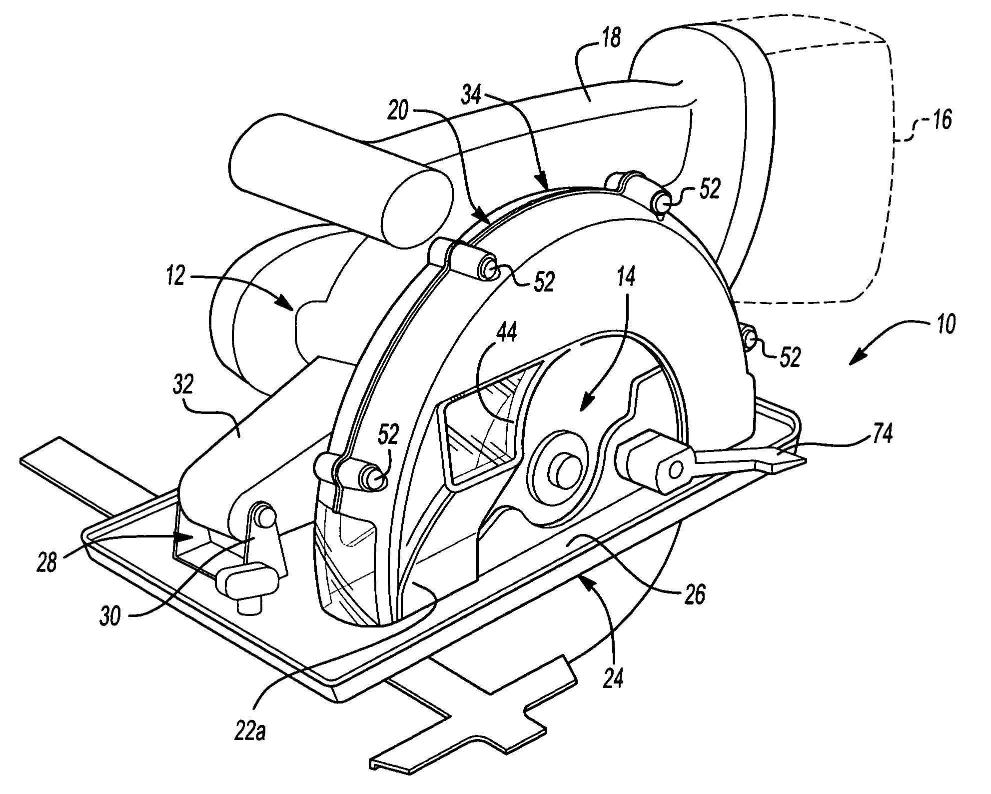
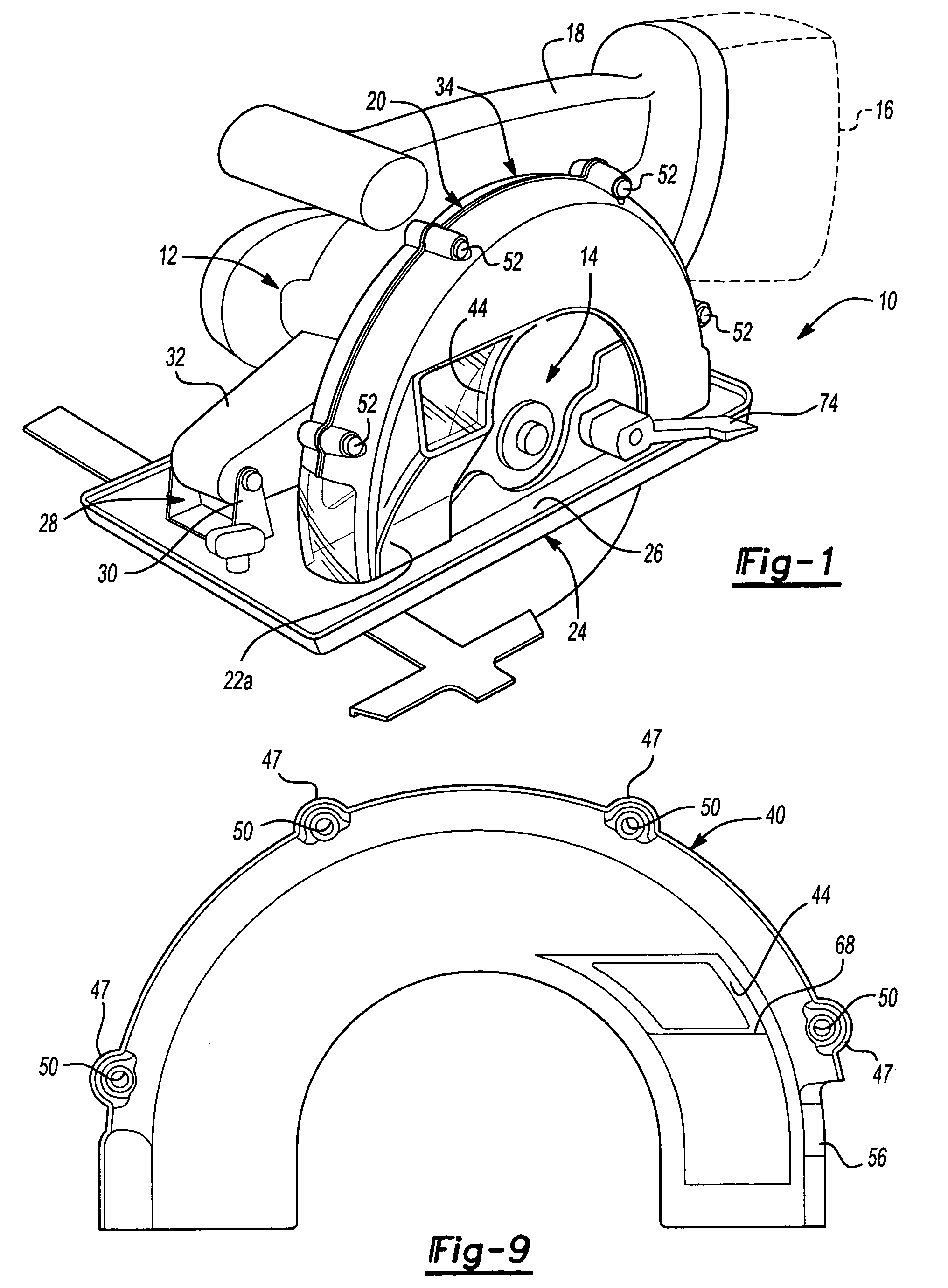
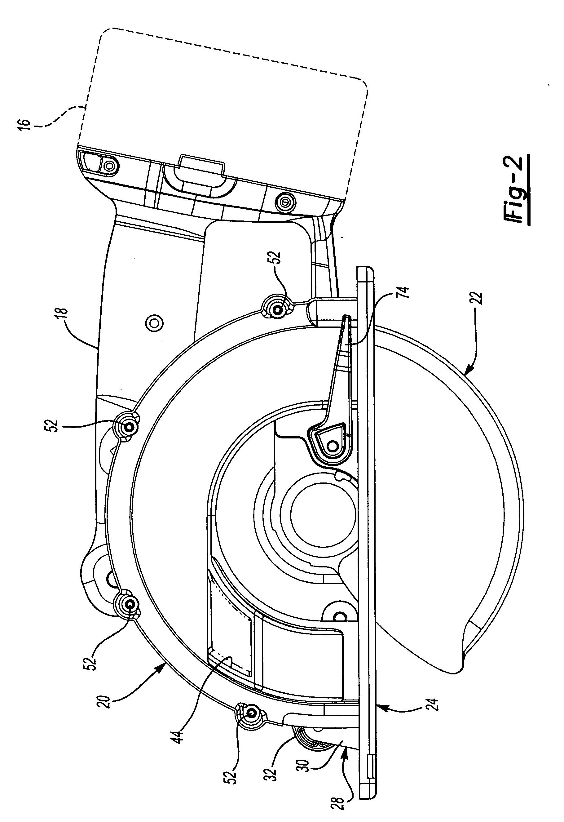
[0036] Referring to the drawings in greater detail, and initially to FIG. 1, a metal cutting power circular saw designated generally by numeral “10” is shown. Saw 10 has a motor 12 which is operably attached to a circular saw blade 14. A battery pack 16 is mounted to a handle portion 18. The battery pack 16 supplies electrical power to motor 12. The upper portion of blade 14 is surrounded by an upper blade guard assembly 20. Upper blade guard assembly 20 is fixedly secured to motor 12. A lower portion of blade 14 is surrounded by a lower saw guard 22. Saw 10 further has a saw shoe 24 defining a planar base with an elongated slot 26 for receiving the circular saw blade 14 therethrough.

[0037] Lower guard 22 exposes the lower portion of blade 14 in a manner that is well known in the art. More specifically, the front e...


PUM

PropertyMeasurementUnit
angleaaaaaaaaaa
angleaaaaaaaaaa
distanceaaaaaaaaaa

Abstract

A metal cutting circular saw is provided with an upper blade guard which includes a first sight window disposed in a first side surface and disposed in a plane angularly offset from a plane of the blade. The upper blade guard also includes a second sight window disposed in the second side surface of the upper blade guard. A light window is disposed in a front portion of the perimeter outer surface of the upper blade guard. The upper blade guard is made from metal and the first and second sight windows and the light window are integrally formed as a one-piece member. The saw shoe and lower blade guard are configured to minimize chip spray from contacting a user.

Description

CROSS-REFERENCE TO RELATED APPLICATIONS [0001] This application is a divisional of U.S. patent application Ser. No. 10 / 474,986, filed on Oct. 16, 2003, which is a US National Stage of International Application No. PCT / US02 / 10519, filed 03 Apr. 2002, which claims the benefit of U.S. application Ser. No. 09 / 827,817, filed 06 Apr. 2001. The disclosures of the above applications are incorporated herein by reference.FIELD OF THE INVENTION [0002] The present invention relates to a circular saw and- more particularly to a metal cutting circular saw having a viewing window on the upper guard and which is specifically designed to protect the user from metal chips. BACKGROUND AND SUMMARY OF THE INVENTION [0003] One of the problems associated with the use of a handheld circular saw is properly aligning the saw so that the desired cut is achieved. Typically, a user will draw a line on the material to be cut. This line represents the location of the desired cut. The problem arises when the user ...

Claims


Application Information

Patent Timeline
Patent Type & Authority Applications(United States)
IPC IPC(8): B23D45/16B27B9/00B27G19/04
CPCB23D45/16B27G19/04B27B9/00Y10T83/828Y10T83/7734
Inventor MOORE, KEITHVAN WAMBEKE, WESTON J.SAYLES, JOEL D.
Owner BLACK & DECKER
Why Eureka
Try Eureka