Optical Blade Clearance Probe

a technology of optical probes and blade tips, applied in the field of improved optical probes, can solve the problems of reducing thrust, requiring additional fuel consumption, and reducing the energy of the system, so as to achieve the effect of maintenance, and reducing the cost of operation

Active Publication Date: 2012-07-19
PRIME PHOTONICS LC
View PDF3 Cites 24 Cited by
  • Summary
  • Abstract
  • Description
  • Claims
  • Application Information

AI Technical Summary

Benefits of technology

[0021]Step (iv) comprises a step of determining a ratio between a rise time in the signal pulse and a rise time in the reference pulse, or comprises a step of determining a ratio between a fall time in the signal pulse and a fall time in the reference pulse, or comprises a step of determining a ratio between a delay time in the signal pulse and a delay time in the reference pulse, or comprises a step of determining a ratio between signal rise time and rise time delay. This method may further comprise the step of minimizing a reflection of said electromagnetic radiation from said optical element back to the reference detector and the signal detector, and the step of varying the optical power of the lens 20 by varying the distance from the ends of the fibers to the lens.

Problems solved by technology

Any gas which travels between the blade tips and the engine shroud represents a significant loss of energy from the system, lowering thrust and requiring the consumption of additional fuel.
Doing so, however, runs the risk of a catastrophic failure occurring if the blades impact the engine shroud.

Method used


Image

  • Optical Blade Clearance Probe
  • Optical Blade Clearance Probe
  • Optical Blade Clearance Probe

Examples


example

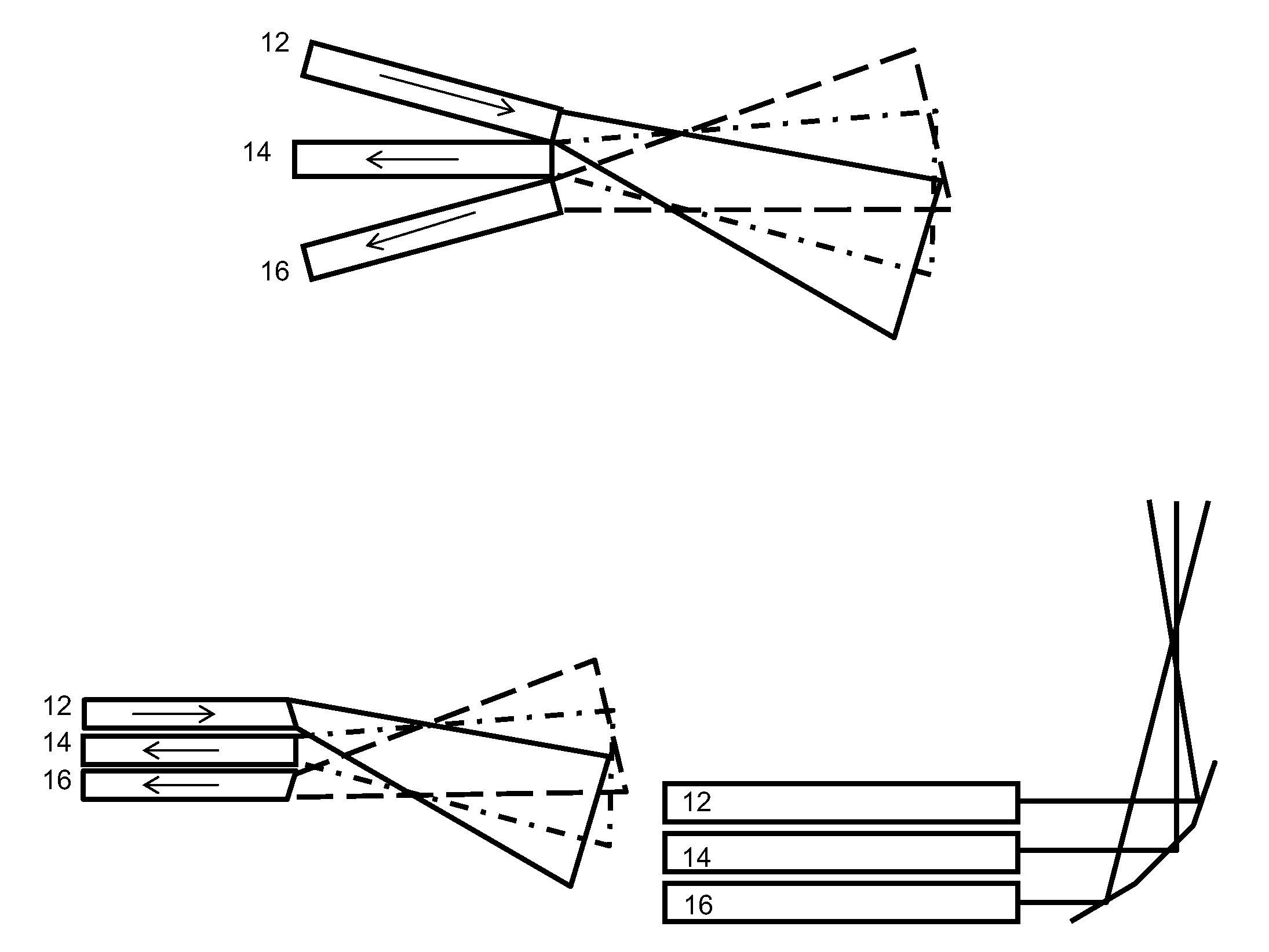
[0067]An experiment was conducted to establish the relationship between the distance between the distal ends of optical fibers 12, 14 and 16 to lens 20 and the dynamic range of probe 10. The fiber to lens distances of about 1.467 mm, 2.25 mm and 2.50 mm were tested. FIG. 13 shows ray trace diagrams of the optical system for three different values of the fiber to lens distance (top=1.467 mm, middle=2.250 mm, bottom=2.500 mm). The horizontal axis of the ray trace diagrams shows distance in millimeters with the left side of lens 20 at 0 mm. The launch point of light beam 18 is off the chart for the middle and bottom diagrams.

[0068]In each of the plots, the solid lines correspond to the path of the launched light, while the dashed line represents the field of view for the reference channel, and the dotted line is the field of view of the signal channel. Although not shown, window 24 is also accounted for, with the exterior face being located at the location of 3.1 mm. The three ray trac...


PUM


Abstract

The sensor comprises a beam of electromagnetic radiation projecting across a gap between the stationary member and the translating member, a reference detector having a reference FOV and a signal detector having a signal FOV. The sensor is to be mounted on the stationary member. The electromagnetic radiation beam, the reference FOV and the signal FOV intersect in a volume including the gap, and the gap is calculated from the reflected electromagnetic radiation received by the reference and signal detectors. The gap can be determined from a ratio between a rise time in the signal pulse and a rise time in the reference pulse, or a ratio between a fall time in the signal pulse and a fall time in the reference pulse, or a ratio between a delay time in the signal pulse and a delay time in the reference pulse, among other features.

Description

CROSS-REFERENCE TO RELATED APPLICATIONS[0001]The present application claims priority under 35 U.S.C. §119(e) to U.S. provisional patent application Ser. No. 61 / 461,180 entitled “Single Lens Variation of the FOCIS Probe” filed on Jan. 14, 2011, U.S. provisional application Ser. No. 61 / 520,953 entitled “FOCIS Based Blade Identification” filed no Jun. 18, 2011, and U.S. provisional application Ser. No. 61 / 520,948 entitled “FOCIS™ Based FOD Detection” field on Jun. 18, 2011, which are incorporated by reference herein in their entireties.STATEMENT REGARDING FEDERALLY SPONSORED RESEARCH OR DEVELOPMENT[0002]This invention was made with government support under U.S. Army contract no. W911W6-08-C-0058 awarded by the Department of the Army. The Government of the United States of America may have certain rights to this invention.FIELD OF THE INVENTION[0003]This invention generally relates to an improved optical probe that measures the distance between a translating member and a stationary memb...

Claims


Application Information

Patent Timeline
Patent Type & Authority Applications(United States)
IPC IPC(8): G01B11/14
CPCG01B11/14G01B11/026
Inventor KOMINSKY, DANIEL
Owner PRIME PHOTONICS LC
Why Eureka
Try Eureka