Visibility Display Device Using an Index-Matching Scheme

a display device and index matching technology, applied in the field of display modules, can solve the problems of reducing the display module's outdoor performance, reducing the power consumption of the display module, and reducing the ratio between the reflected light containing picture information so as to improve the contrast in the image, improve the effect of the relationship between the reflected light and the reflected light without picture information

Inactive Publication Date: 2008-09-25
SONY ERICSSON MOBILE COMM AB
View PDF9 Cites 28 Cited by
  • Summary
  • Abstract
  • Description
  • Claims
  • Application Information

AI Technical Summary

Benefits of technology

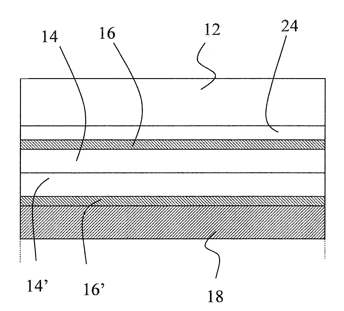
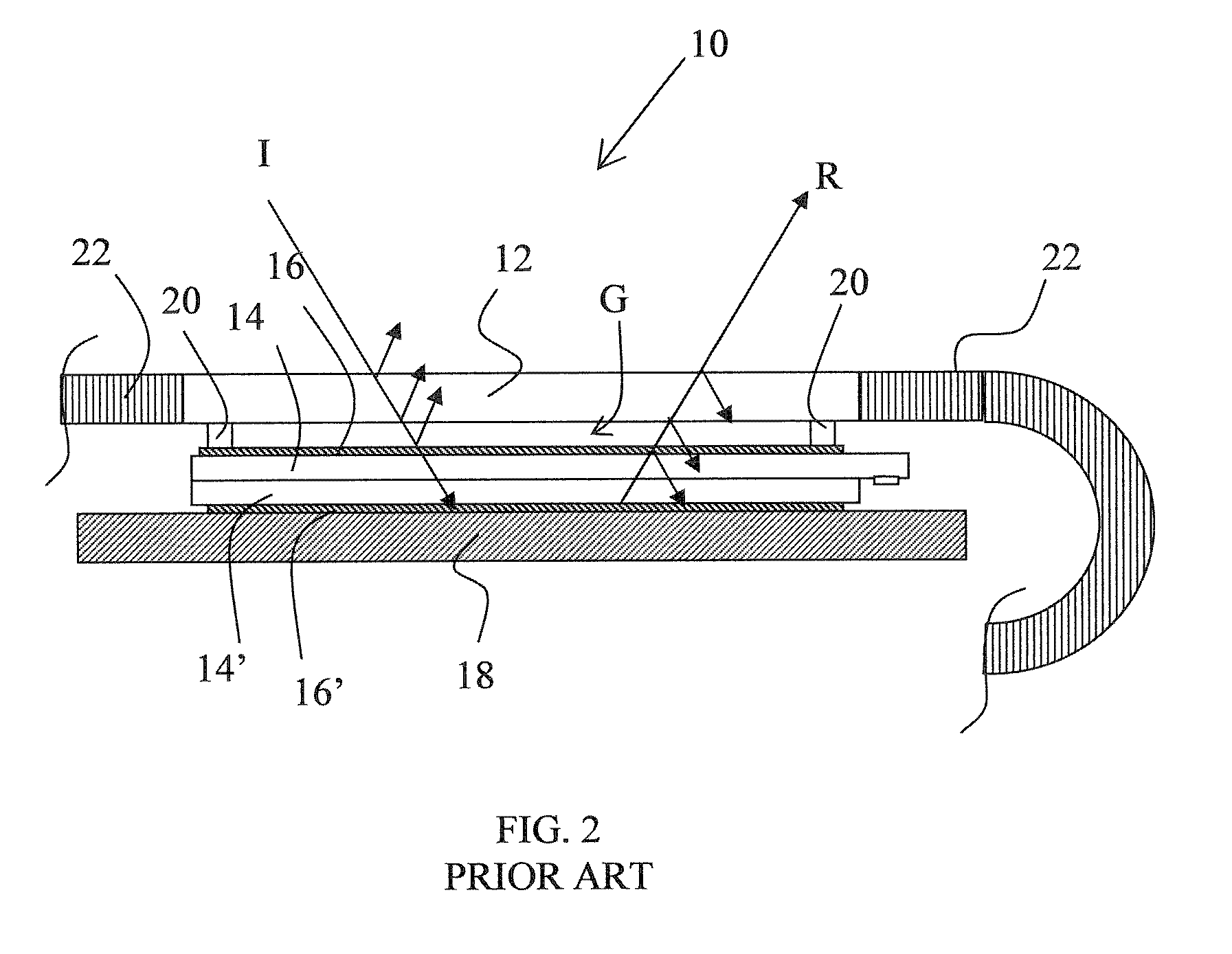
[0026]In a typical embodiment, the luminance loss in reflections from the back light will only be 4% in the best case, i.e. when the angle of incidence is perpendicular and the material of the intermediate layer is selected in such a way that the refraction index of the intermediate layer matches the refraction indexes of the material of the front window and the display unit. Consequently, 96% of the backlight luminance, containing the picture information, will reach the viewer. In correspondence, only 4% of the incoming light will be reflected without reaching the display unit and thus does not contain any picture information. Thus 96% of the incoming light will reach the display unit, and 96%*5%*96%≈4.6% of the incoming light will be reflected from the display unit and contain the picture information. Consequently, the ratio between the reflected light containing picture information and the reflected light without picture information is improved.
[0027]When the transmitted light fr

Problems solved by technology

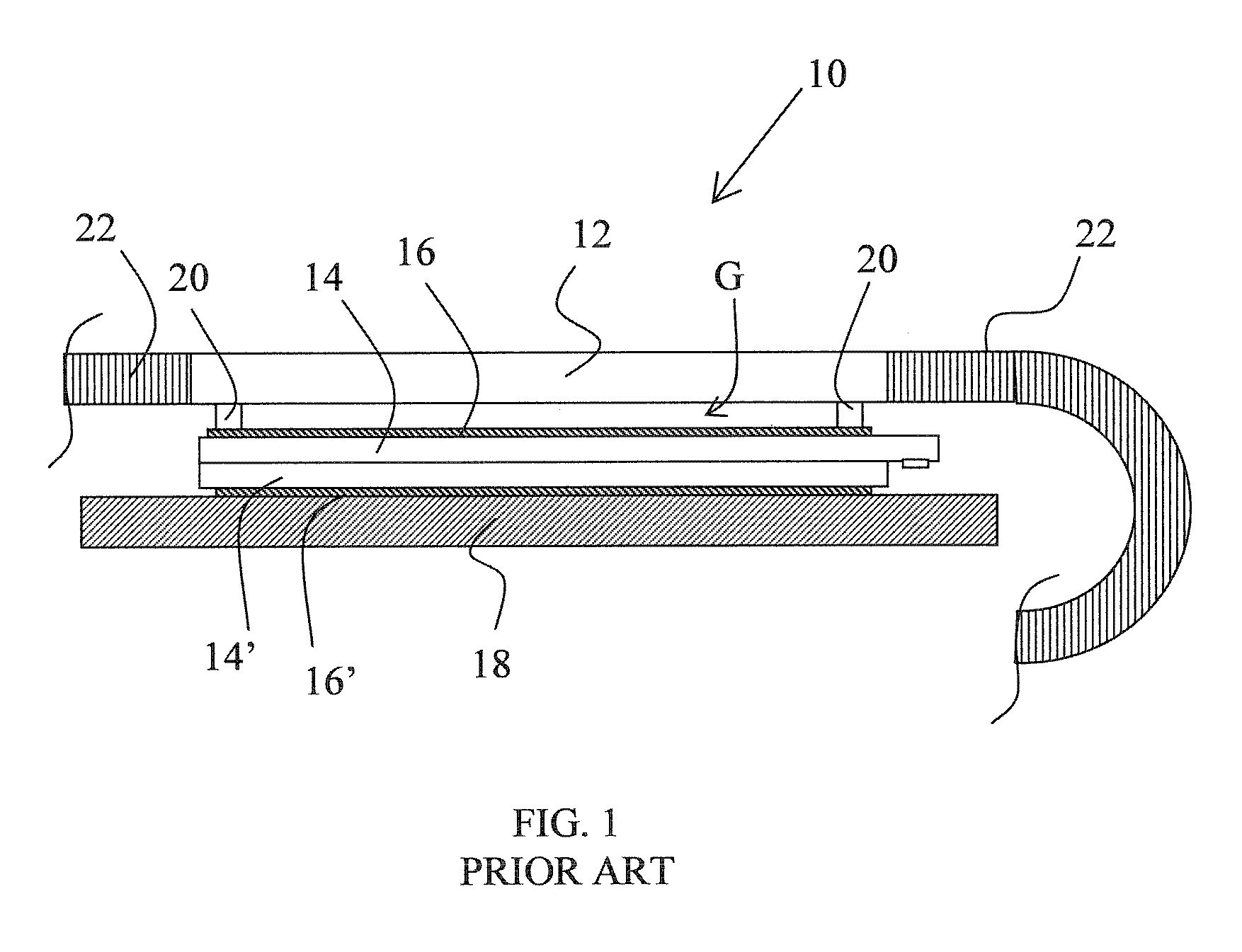
One problem with the prior art display modules is the luminance losses due to reflection of light in the interface between material layers in the display modules having different refraction indexes.
An aspect of the aforementioned problem is that roughly 12% of the backlight luminance, i.e. the light from the display unit to the viewer, will be lost before reaching the eye due to reflection in the interface between the display unit and the air gap, and in the interface between the air gap and the front window.
Another aspect o

Method used


Image

  • Visibility Display Device Using an Index-Matching Scheme
  • Visibility Display Device Using an Index-Matching Scheme
  • Visibility Display Device Using an Index-Matching Scheme

Examples


Embodiment Construction

[0040]The present description relates to the field of display modules for use in electronic devices, and in particular radio communication terminals. The term radio terminal or communication terminal, also denoted terminal in short in this disclosure, includes all mobile equipment devised for radio communication with a radio station, which radio station also may be mobile terminal or e.g. a stationary base station. Consequently, the term radio terminal includes mobile telephones, pagers, communicators, electronic organisers, smart phones, PDA:s (Personal Digital Assistants), laptop computers, and DECT terminals (Digital Enhanced Cordless Telephony). Hence, although the structure and characteristics of the invention are mainly described herein, by way of example, in the implementation in a mobile phone, this is not to be interpreted as excluding the embodiment and implementation of the invention in other types of electronic devices. In particular, the invention is suitable for use, t...


PUM


Abstract

Display module (10) for use in an electronic device, comprising a front window (12) and a display unit (13, 100), wherein an intermediate layer (24) of transparent material is sandwiched between the front window (12) and the display unit (13, 100). The intermediate layer (24) consists of a material which is selected taking the material of the front window (12) into consideration in order to minimize reflection at the interface between the front window (12) and the intermediate layer (24). The intermediate layer (24) consists of one or more layers whose refractive indices are chosen so that they closely match the refractive indices of the front window or the display unit.

Description

TECHNICAL FIELD OF THE INVENTION [0001]The present invention relates to an arrangement for display modules for use in electronic devices, such as portable radio communication terminals. In particular, the present invention is concerned with display modules having improved brightness and reflectance properties, and with increased suitability for use in small size electronic devices.DESCRIPTION OF RELATED ART [0002]The first commercially attractive cellular telephones or terminals were introduced in the market at the end of the 1980's. Since then, a lot of effort has been made in making smaller terminals, with much help from the miniaturisation of electronic components and the development of more efficient batteries. Today, numerous manufacturers offer pocket-sized terminals with a wide variety of capabilities and services, such as packet-oriented transmission and multiple radio band coverage.[0003]In mobile phones of today, a front window is typically used to protect the display unit...

Claims


Application Information

Patent Timeline
IPC IPC(8): G02B5/00
CPCG02F1/133502G02F1/133603G02F2202/28G02F2201/38G02F2001/133311G02F1/133311
Inventor GRIP, MARTINHUNT, ALEXANDEREK, MARTIN
Owner SONY ERICSSON MOBILE COMM AB
Why Eureka
Try Eureka