Gear transmitting device and electronic apparatus

a technology of electronic equipment and transmitting device, which is applied in the field of gear transmitting device and electronic equipment, can solve the problems of not meeting the required level of geometric accuracy, and achieve the effect of reducing the size of the transmitting device and lowering the cos

Inactive Publication Date: 2005-08-18
SEIKO INSTR INC
View PDF11 Cites 3 Cited by
  • Summary
  • Abstract
  • Description
  • Claims
  • Application Information

AI Technical Summary

Benefits of technology

[0031] As another preferable embodiment of the gear transmitting device of the invention, the involute tooth gear or the cycloidal tooth gear may be placed on the same axis as one of the paired arc-circular tooth gears for oscillation together. If this is the case, the pair of arc-circular tooth gears can be combined together with the involute tooth gear or the cycloidal tooth gear, thereby favorably rendering the gear transmitting device downsized.
[0032] As still ano

Problems solved by technology

The arc-circular tooth gear is required to be accurate in shape, b

Method used


Image

  • Gear transmitting device and electronic apparatus
  • Gear transmitting device and electronic apparatus
  • Gear transmitting device and electronic apparatus

Examples


first embodiment

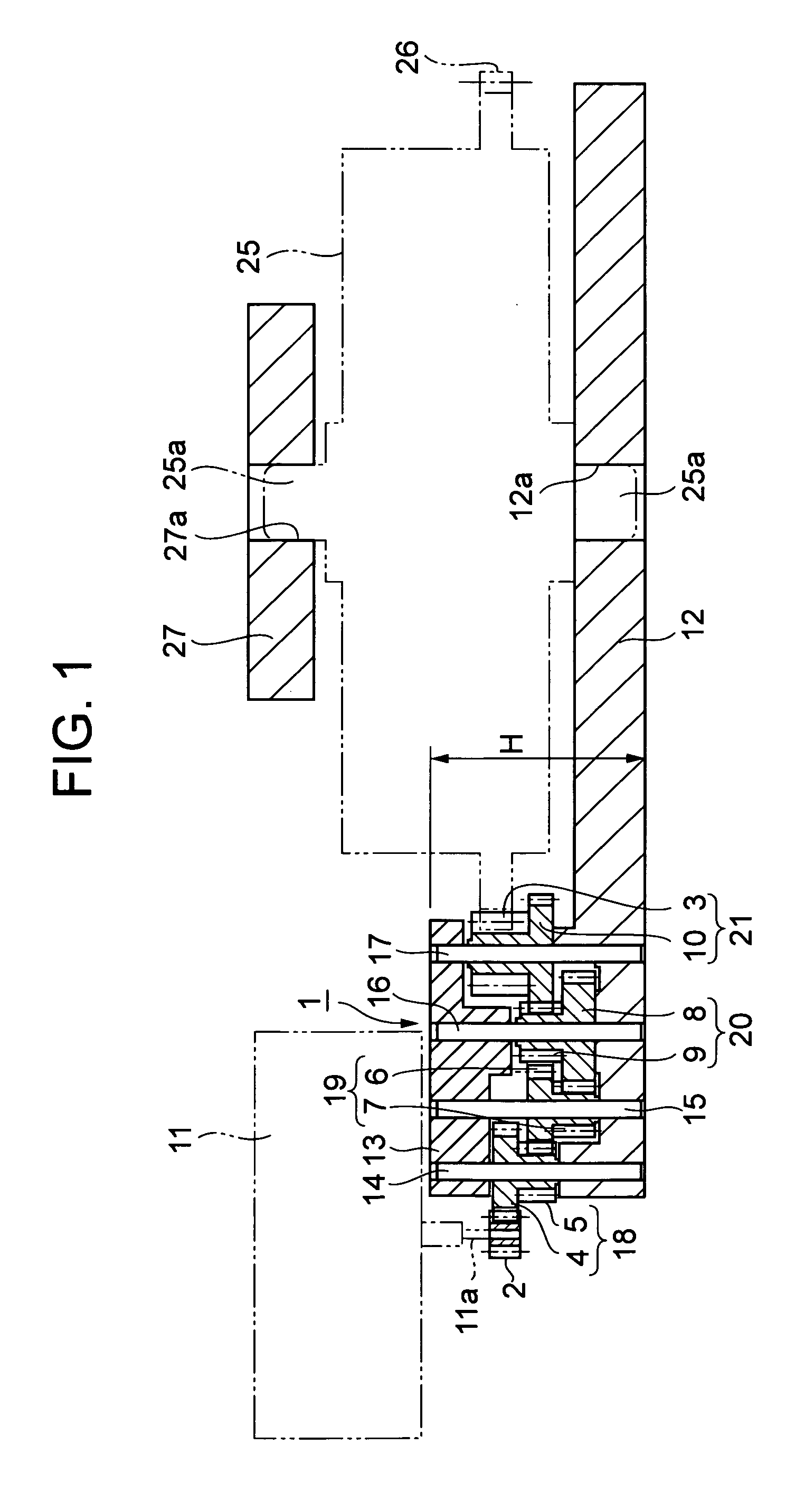
[0058] By referring to FIGS. 1 to 6, the invention is described.

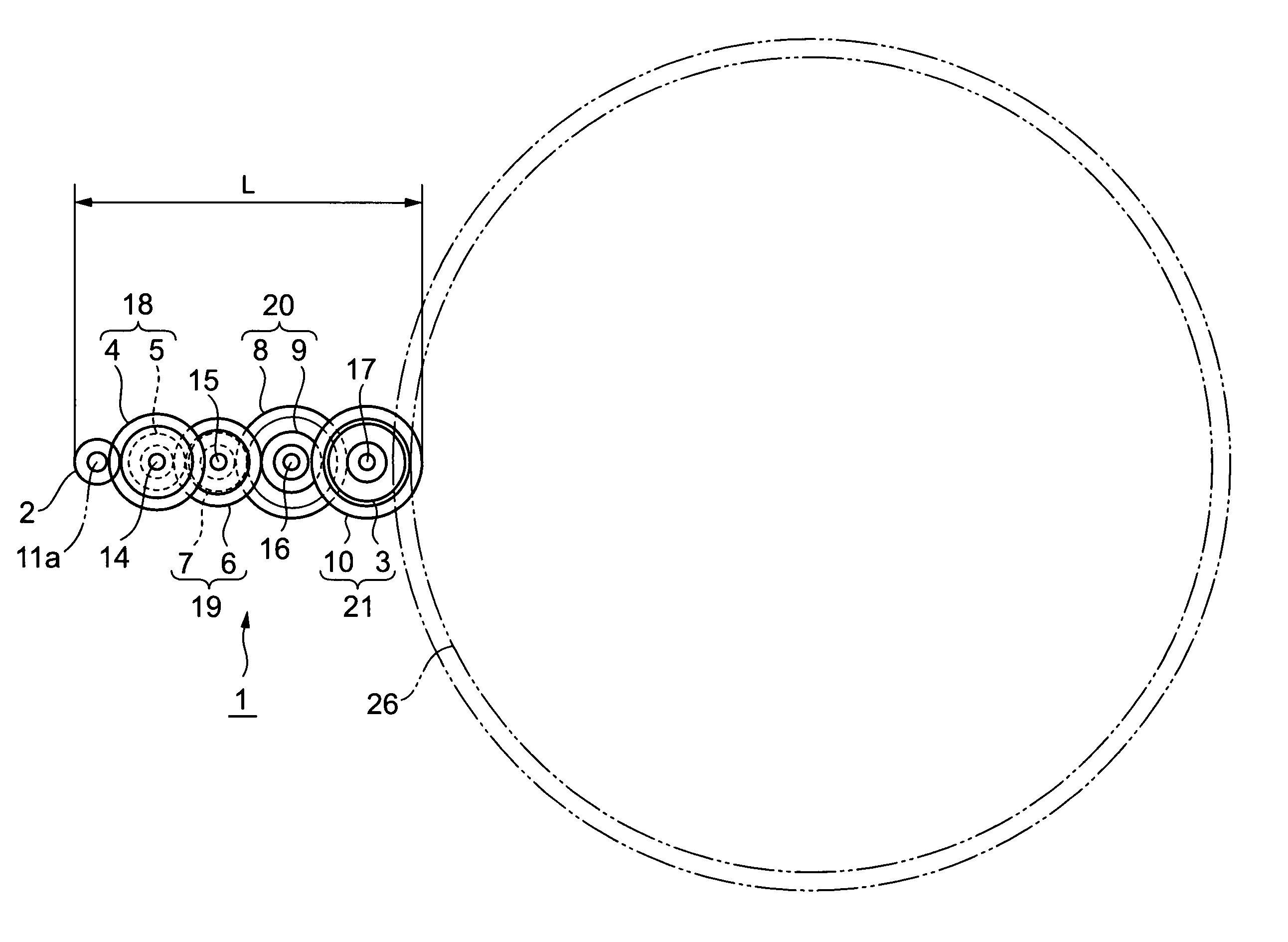
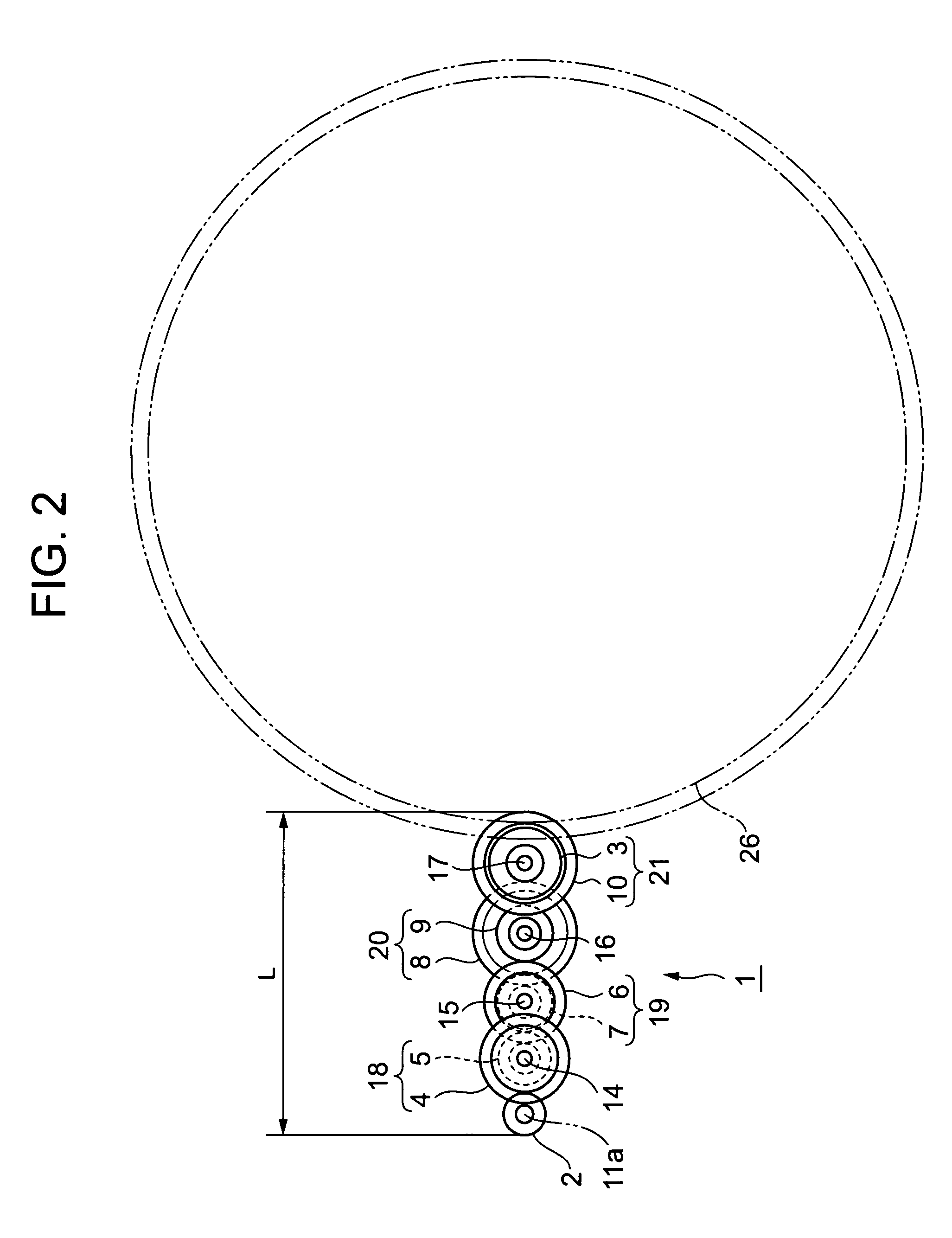
[0059] A gear transmitting device denoted by a reference numeral 1 in FIGS. 1 and 2 is provided with an output gear 3, an input gear 4, and first to sixth intermediate gears 5 to 10 for transmitting oscillation movement to both the input and output gears 4 and 3 by three-stage deceleration.

[0060] As shown in FIG. 1, the input gear 4 is engaged with a drive gear 2, which is attached to a drive section, e.g., an oscillation axis 11a of a motor 11. The motor 11 is exemplified by various types of motors, including electrical motors such as ultrasonic motor and step motor, air motors, hydraulic motors, or others.

[0061] As shown in FIG. 2, the output gear 3 and the intermediate gears 5 to 10 are placed between first and second support members 12 and 13, both of which have the shape of a plate, for example. That is, across the first and second support members 12 and 13 facing each other, first to fourth axes 14 to 17 are fix...

second embodiment

[0075] In the second embodiment, the fourth gear unit 21 includes the output gear (small gear) 3, the sixth intermediate gear (large gear) 10, and the fourth axis 17, all of which are formed in a piece. The output gear 3 oscillates with the sixth intermediate gear 10, and the fourth axis 17 protrudes from the output gear 3 and the sixth intermediate gear 10 for their support. Such a fourth gear unit 21 is attached, to freely oscillate, to the bearing hole 12a of the first support member 12 and the bearing hole 27a of the third support member 27 by inserting the fourth axis 17 thereinto, respectively. Alternatively, for attachment of the fourth gear unit 21 to freely oscillate, the bearing holes 12a and 27a may be each attached with a bearing to support the fourth axis 17 supporting the output gear 3 and the sixth intermediate gear 10. Such a structure of the fourth gear unit 21, i.e., the large and small gears are coaxially formed in a piece, is applied to the first to third gear un...

third embodiment

[0078] In the third embodiment, in the fourth gear unit 21, the output gear (small gear) 3 is separately provided, for oscillation together, from the sixth intermediate gear (large gear) 10. These two components are assembled together so that the fourth gear unit 21 is derived. For the assembly purpose, the sixth intermediate gear 10 has a tube portion 28 protruding from the center part of one plane to the other for support by the fourth axis (not shown in FIG. 8, and refer to the reference numeral 17 in FIGS. 1 and 2) to freely oscillate. Around the tube portion 28, the output gear 3 is attached with a good fit. The structure of this fourth gear unit 21 is applied to the first to third gear units, which are not shown in FIG. 8.

[0079] As an alternative structure to the above, the tube portion 28 to be supported by the fourth axis (not shown in FIG. 8, and refer to the reference numeral 17 in FIGS. 1 and 2) to freely oscillate may be made to protrude from the center part of a plane o...


PUM


Abstract

A gear transmitting device has such a structure as including an input gear, an output gear, and one or more intermediate gears for transmitting gear oscillation to the input and output gears. The gear transmitting device is also provided with a gear train including the input gear for transmitting oscillation to the output gear. The gear train includes, for gear engagement, one or more pairs of arc-circular tooth gears, and an involute tooth gear or a cycloidal tooth gear. With such a structure, the gear transmitting device can be reduced in size, and accordingly an electronic apparatus incorporating the gear transmitting device can be also reduced in size.

Description

BACKGROUND OF THE INVENTION [0001] 1. Field of the Invention [0002] The present invention relates to a gear transmitting device for decelerating or accelerating the oscillation speed using a plurality of gears for transmission, and an electronic apparatus incorporating the gear transmitting device to drive a to-be-driven member using a gear driving device. [0003] 2. Description of the Related Art [0004] For moving a date indicator provided to a watch with date indication, conventionally used is a gear transmitting device of a type including a string of arc-circular tooth gears. For details, refer to Patent Document 1 (JP-A-11-281772, paragraphs 0002 to 0003). [0005] In the general industrial fields other than the field of watch, the popular type of a gear transmitting device is the one including a string of only involute tooth gears. Another popular type is a gear transmitting device including a string only of cycloidal tooth gears. [0006] The issue here is that the gear transmittin...

Claims


Application Information

Patent Timeline
IPC IPC(8): G04B19/02F16H1/20F16H1/24
CPCY10T74/19651F16H1/20F21S8/085F21V3/049F21W2131/103
Inventor SUZUKI, MAKOTOSUZUKI, KENJISATODATE, TAKAYUKIHASEGAWA, HARUHIKO
Owner SEIKO INSTR INC
Why Eureka
Try Eureka