Hydrogen Storage System and Method of Operation Thereof

a hydrogen storage and fuel cell technology, applied in the direction of electrochemical generators, container discharge methods, lighting and heating apparatuses, etc., can solve the problems of urfc′′s being typically limited and reducing efficiency

Inactive Publication Date: 2005-08-18
PROTON ENERGY SYST
View PDF7 Cites 38 Cited by
  • Summary
  • Abstract
  • Description
  • Claims
  • Application Information

AI Technical Summary

Benefits of technology

[0007] In one aspect of the invention, a method for operating a high pressure gas storage system includes the steps of opening a first valve on a first high pressure gas storage container. Releasing gas from the first storage container and closing the first valve in response to a predetermined operating parameter. Opening a second valve on a second high pressure gas storage container and releasing gas from the second storage container. Then finally closing the second valve in response to the predetermined operating parameter. The process may optionally be repeated for each container in the gas storage system until the gas is depleted from the storage system.

Problems solved by technology

However, since the process must be completely reversible within the component, neither of the electrodes can be optimized for a particular generation mode resulting in efficiency losses.
Due to efficiency issues and cost considerations, URFC″s are typically limited to aerospace or geographically remote applications where the size and weight parameters are paramount.

Method used


Image

  • Hydrogen Storage System and Method of Operation Thereof
  • Hydrogen Storage System and Method of Operation Thereof
  • Hydrogen Storage System and Method of Operation Thereof

Examples


Embodiment Construction

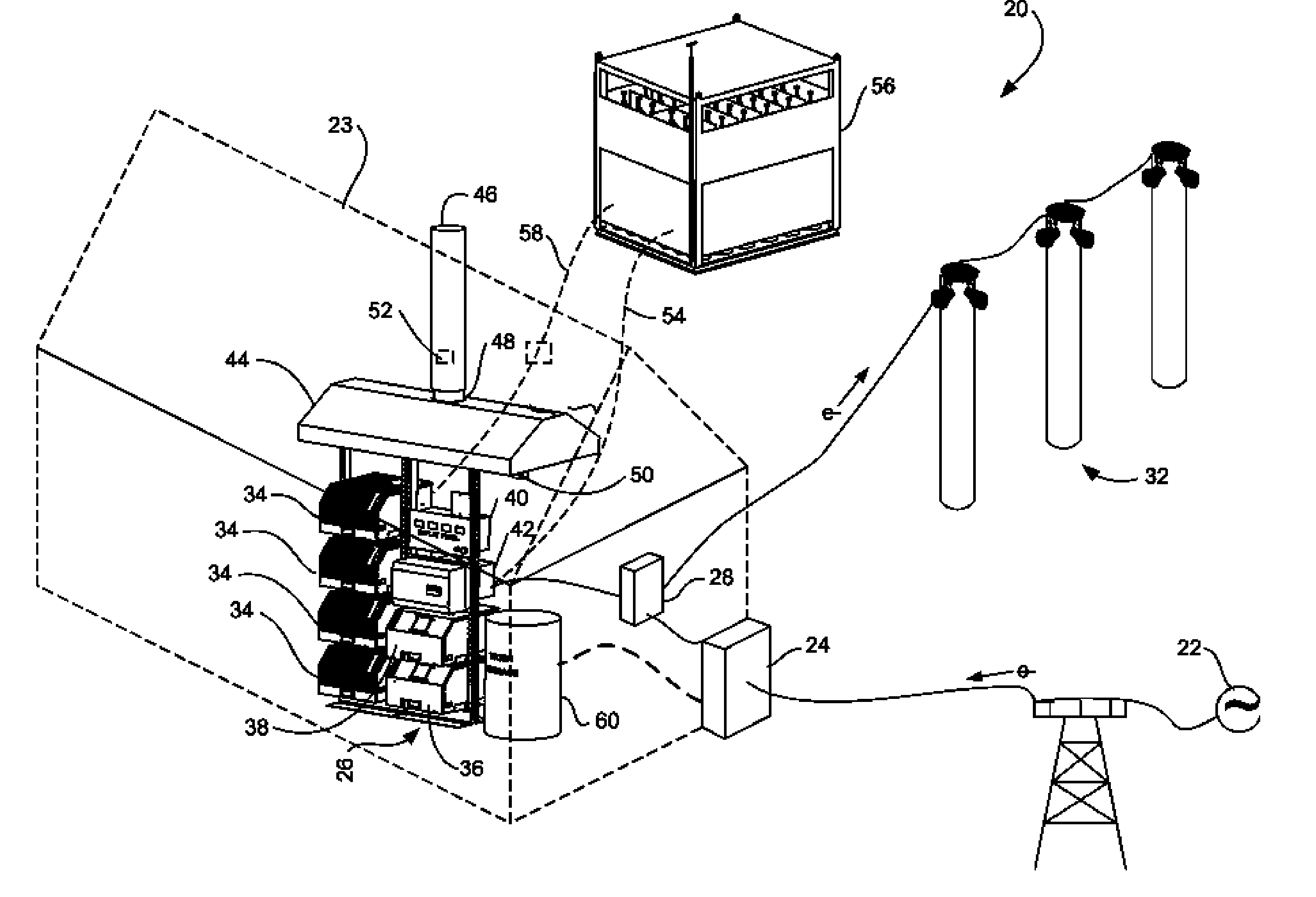
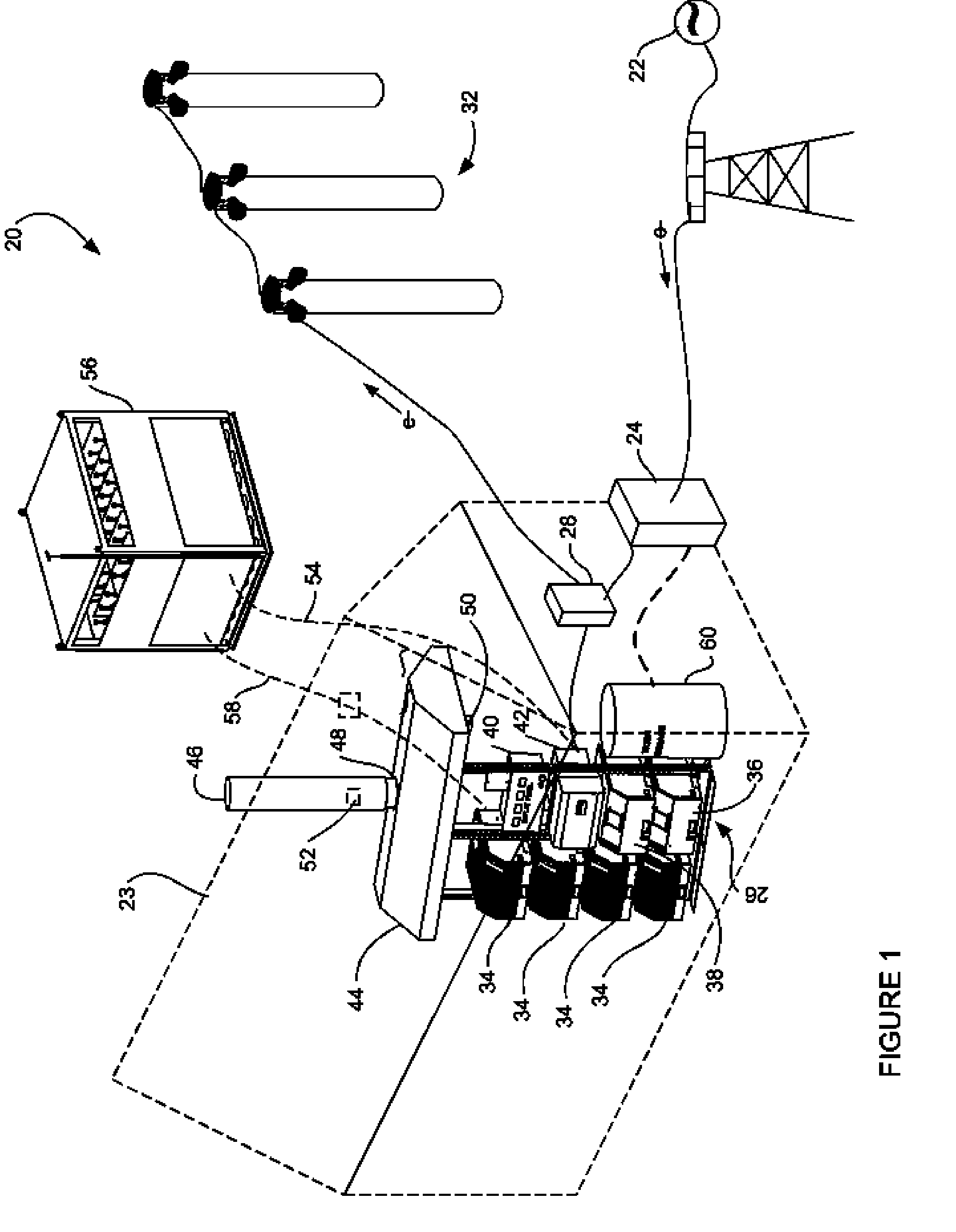
[0037] As shown in FIG. 1, the regenerative fuel cell system 20 of the present invention receives power from an external source 22 through an electrical panel 24. The panel 24 divides the electricity with a portion of the electrical power being provided to the generating system 26 and the remainder being provided to a load center 28. The load center 28 transmits electrical power to a load 30, which is illustrated herein by a series of lights 32. The load center 28 also receives power from the generating system 26.

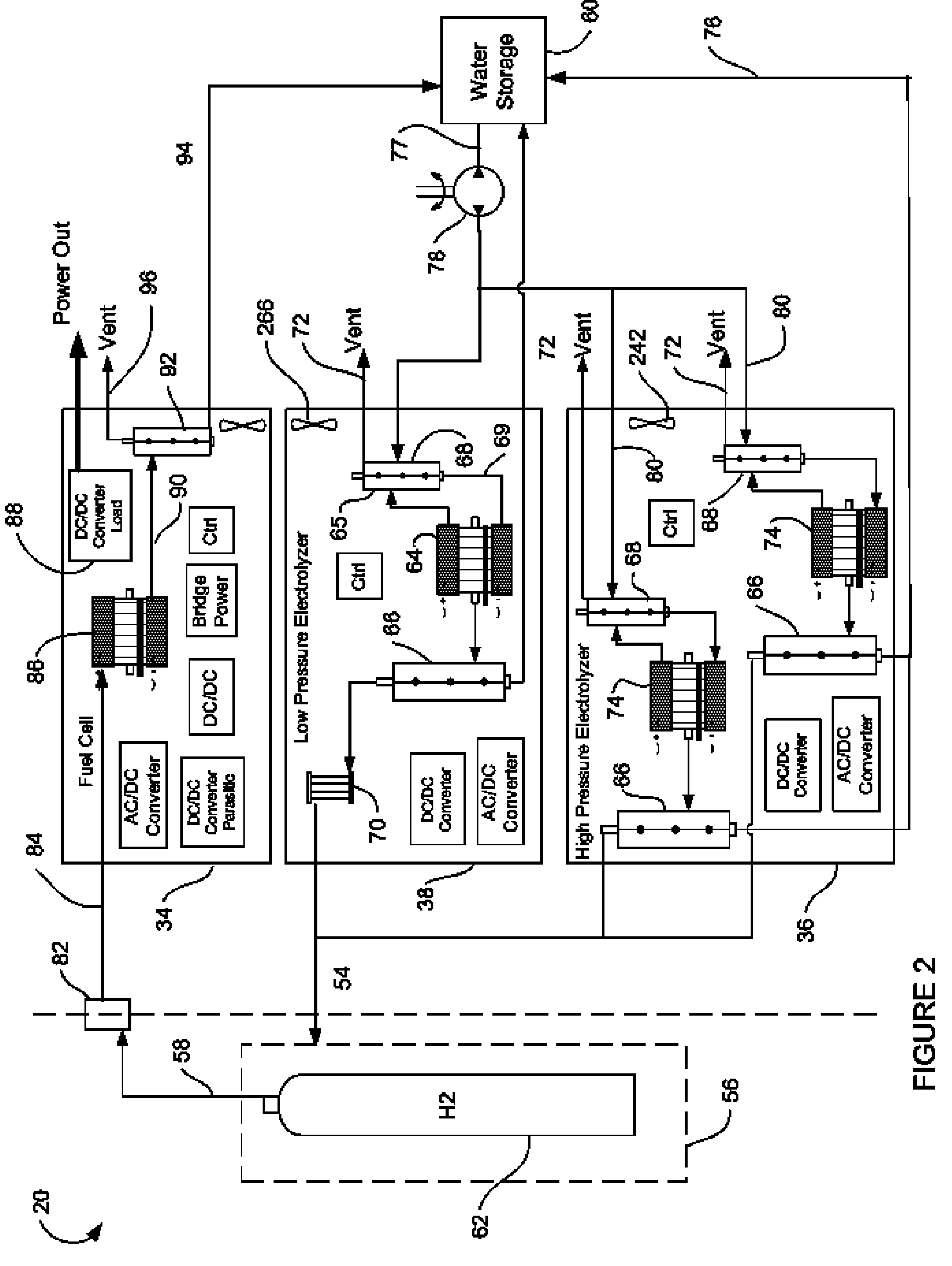
[0038] As will be described in more detail herein, the generating system 26 includes power generating modules 34, and hydrogen generators 36, 38. An interface module 40 provides the system operator a central interface for the system 20. Additionally, an inverter 42 converts DC electric power generated by the power generators 34 into AC power which is provided to the load center 28 in the event of a power failure by the external source 22. An optional water storage tank 60 ...


PUM

PropertyMeasurementUnit
pressureaaaaaaaaaa
pressureaaaaaaaaaa
pressureaaaaaaaaaa

Abstract

A regenerative fuel cell system is provided having at least one hydrogen storage container fluidly coupled to at least one hydrogen generator and at least one power generator. Each power generator further includes a fuel cell fluidly coupled to the hydrogen storage container, an electric energy storage device, and an unregulated dc bus electrically connected to said fuel cell and said electric storage device. The system further provides for a health monitoring system for determining the occurrence of critical events which may necessitate the disabling of the system.

Description

CROSS REFERENCE TO RELATED APPLICATIONS [0001] This application is a continuation in part and claims the benefits of Regenerative Fuel Cell System and Method of Operation Thereof application Ser. No. 10 / 708,165 filed Feb. 12, 2004, the entire contents of which are incorporated herein by reference.FIELD OF INVENTION [0002] The present invention relates to a regenerative fuel cell power generation system, and in particular to a system having multiple fuel cell and electrolysis cell modules of different configurations. BACKGROUND OF THE INVENTION [0003] Regenerative fuel cell systems provide a reversible electrochemical process for using electricity to convert water into hydrogen and oxygen and then reversing the process to combine the hydrogen and oxygen to create electricity. Typically, these systems have a membrane electrode assembly (“MEA”) that includes an ion conducting polymer membrane sandwiched between two electrodes containing a catalyst material. In fuel generation, or elect...

Claims


Application Information

Patent Timeline
Patent Type & Authority Applications(United States)
IPC IPC(8): F17C7/00F17C13/02F17C13/08H01M8/04H01M8/18H01M16/00
CPCF17C7/00Y02E60/528F17C13/084F17C2201/0104F17C2201/032F17C2201/054F17C2203/0617F17C2203/0639F17C2203/0663F17C2205/0107F17C2205/0111F17C2205/0126F17C2205/013F17C2205/0142F17C2205/0146F17C2205/0176F17C2205/0332F17C2205/0341F17C2221/012F17C2223/0123F17C2223/035F17C2223/036F17C2225/0123F17C2225/035F17C2225/036F17C2250/032F17C2250/043F17C2260/042F17C2265/012F17C2270/0763H01M8/04089H01M8/04201H01M8/04208H01M8/18H01M16/003Y02E60/321F17C13/025Y02E60/32Y02E60/50Y10T137/0396Y10T137/4673Y10T137/4857
Inventor PORTER, STEPHEN CHARLESLILLIS, MARK ANDREWHALTER, DEAN EDWINSHIROMA, IRIS LIANENOMIKOS, SPYROS
Owner PROTON ENERGY SYST
Why Eureka
Try Eureka