
Flexible and extendable plumbing trap device

Inactive Publication Date: 2005-08-18
RENNER BRIAN K
View PDF24 Cites 16 Cited by
  • Summary
  • Abstract
  • Description
  • Claims
  • Application Information

AI Technical Summary

Benefits of technology

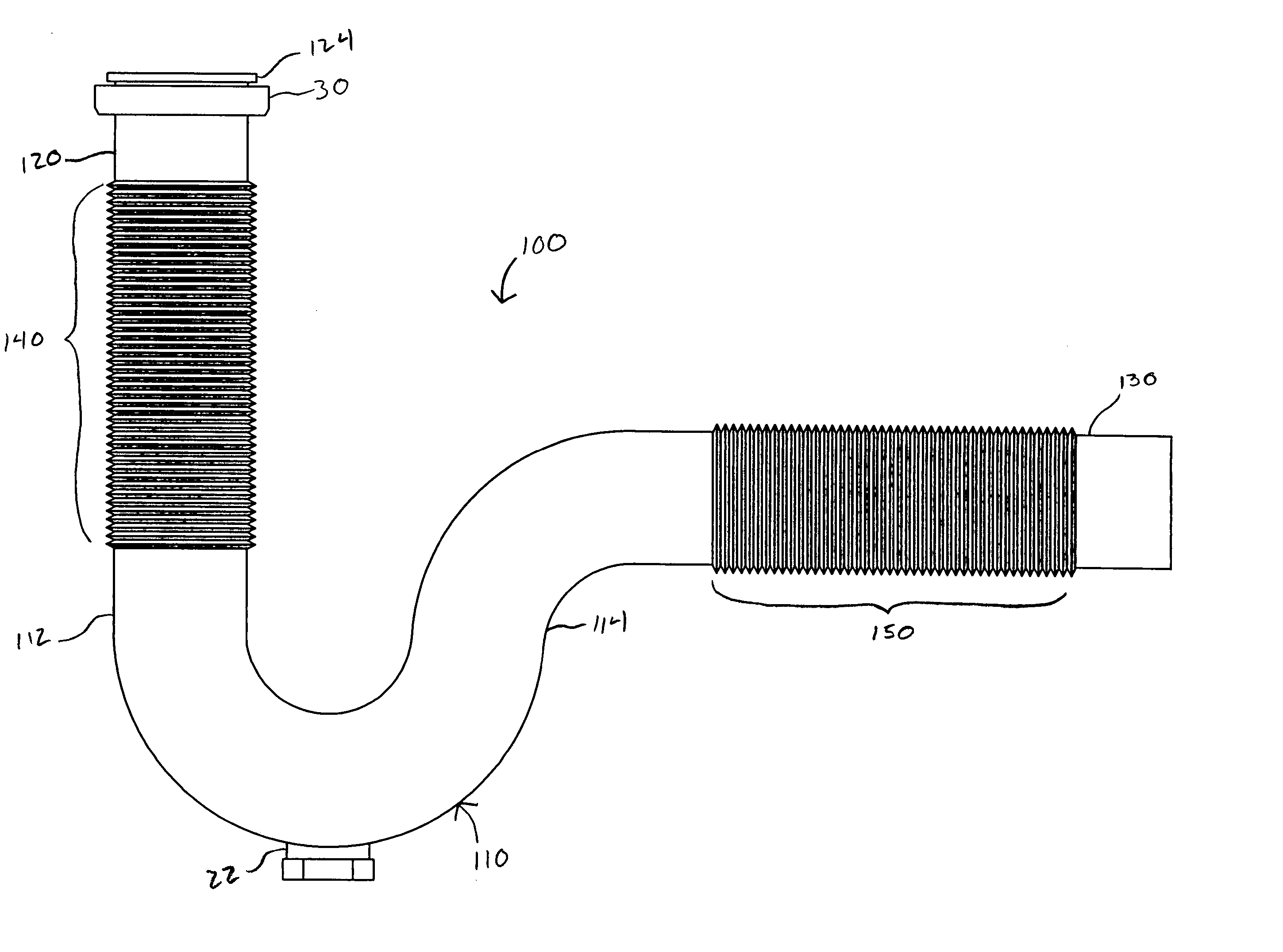
[0012] The flexible sections are formed from a portion of the tubing that has been shaped to form pleats or corrugations. The flexible sections therefore present a length of tubing having a structure that may be described as an accordion or bellows. The flexible sections provide the inlet and outlet arms with sufficient flexibility, and axial extension and retraction, to facilitate installation of the plumbing trap device between plumbing fixtures, such as drains and drain outlets, of various spacings.

Problems solved by technology

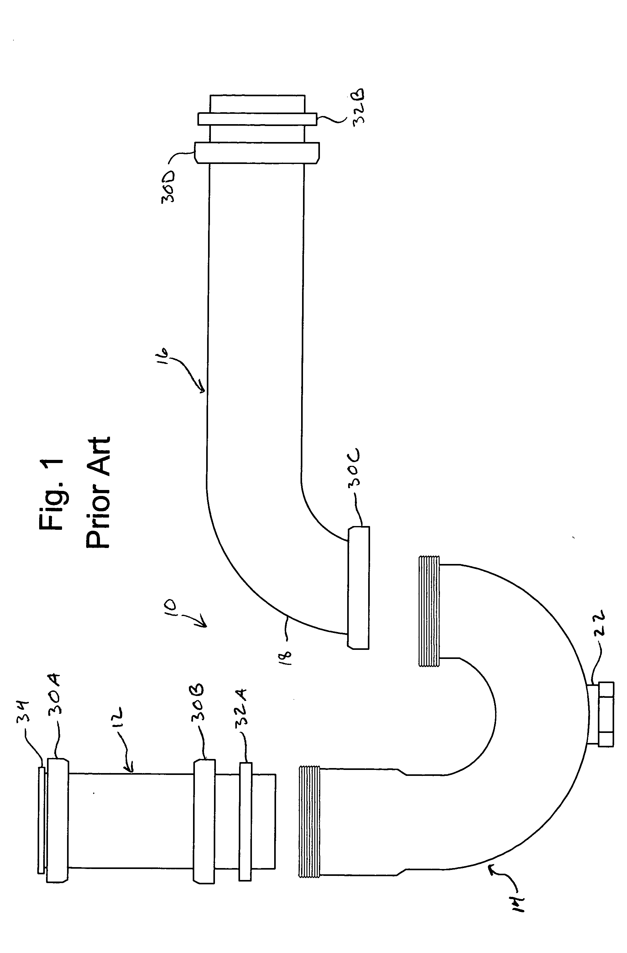
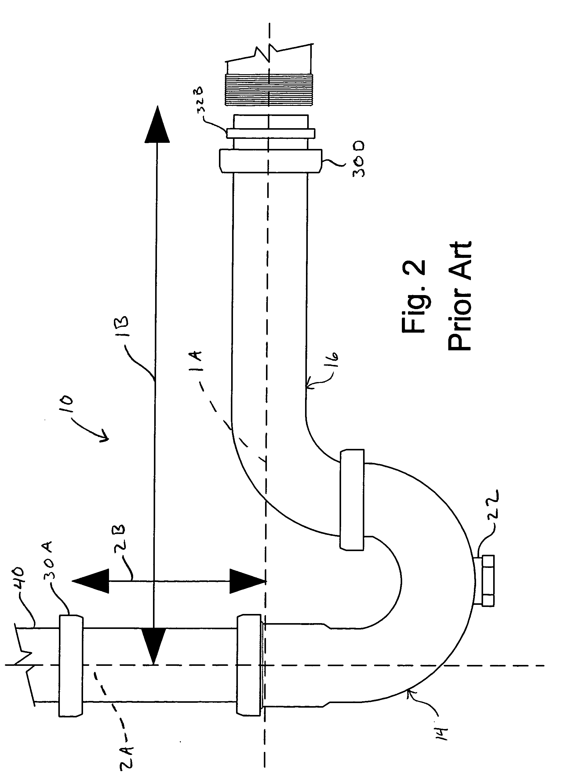
Unfortunately, the axes are often not in perpendicular alignment and often the space provided between the tail piece and drain outlet is not large enough to readily accommodate plumbing traps in the prior art.
These traps present structures similar to curved lengths of rubber or soft plastic tubing and therefore, while providing flexibility, also present some disadvantages.
Apart from being the less desired method of attaching household drain fixtures, hose clamps are typically formed of metal components which are liable to rust under the damp conditions usually associated with plumbing drains.
A further problem presented by flexible traps, such as those disclosed in Lamond and Bresnahan, is that the soft material does not lend itself to the inclusion of a clean out aperture in the lower portion of the trap.
Both the lack of a clean out aperture, and the flexibility of the trap itself, often render such devices unusable as they do not pass common plumbing code enacted by most local governments.
While providing flexibility, such arrangements also present disadvantages in that the flexible trap portion will not meet most plumbing code restrictions, is not amenable to the provision of a clean out plug, and due to the physical structure of the pleats, tends to collect debris within the trap itself necessitating dismantling the trap.
While presumably solving a portion of the problem presented, such structures still present deficiencies in that they require assembly of multiple components on-site and specifically disclose the need to cut portions of the tail extension to accommodate alignment in various situations.
The patent, however, does not disclose a section that also provides extension and compression of the flexible section, nor does it disclose a unitary body having flexible and extensible sections incorporated into both the inlet arm and the outlet arm.

Method used


Image

  • Flexible and extendable plumbing trap device
  • Flexible and extendable plumbing trap device
  • Flexible and extendable plumbing trap device

Examples


Embodiment Construction

[0028] Referring more particularly to the drawings, and initially to FIGS. 3-8, there is shown a unitary, flexible and extendable plumbing trap device 100 including a generally U-shaped trap section 110 having inlet 112 and outlet 114 portions, a tubular inlet arm 120 communicating with the inlet 112 and a tubular outlet arm 130 communicating with the outlet 114, the device thereby providing a plumbing trap device 100 for receiving waste water or other fluid from the tail piece of a drain into the inlet arm 120 and delivering the fluid through the trap section 110 and outlet arm 130 to a drain outlet. To aid in the alignment of the plumbing trap device 100, when connected to the drain tail piece and drain outlet, both the inlet arm 120 and outlet arm 130 include flexible and extendable sections, 140 and 150 respectively, including a plurality of corrugations throughout the length of each section to allow the inlet arm and outlet arm 130 to flex, extend, and retract or compress to ad...


PUM


Abstract

A plumbing trap having flexible and extensible arms that allow installation of the trap between drain tail pieces and drain outlets of various spacings and orientations while reducing the need for cutting trap elements during installation or assembly of a trap from multiple components.

Description

FIELD OF THE INVENTION [0001] The invention relates to plumbing fixtures and, in particular, to a plumbing trap device with portions that provide sufficient flexibility and axial extension and retraction to allow the trap to be installed between plumbing fixtures, such as drains and drain outlets, of various spacings. The present invention also relates to a plumbing trap device having flexible and extensible inlet arm and outlet arm sections for facilitating installation of the trap between drain and outlet fixtures of various spacings without the need for assembling the trap from multiple components, or cutting the components, to fit a particular spacing arrangement. BACKGROUND OF THE INVENTION [0002] When installing a common plumbing trap, a plumber must be able to align the inlet of the trap with the tail piece of the plumbing fixture so that they are in straight vertical alignment, often incorporating an intermediate extension tube also referred to as a tail extension piece. Bec...

Claims


Application Information

Patent Timeline
IPC IPC(8): F16K13/00F16L55/24
CPCF16L55/24E03C1/284E03C1/122Y10T137/4576
Inventor RENNER, BRIAN K.
Owner RENNER BRIAN K
Learn More