Structure for expanding thermal conducting performance of heat sink

a technology of thermal conductivity and heat sink, which is applied in the direction of basic electric elements, semiconductor devices, lighting and heating apparatus, etc., can solve the problems of restricting the heat dissipation effect of the fins, obstructing the heat conductance of the heat sink, etc., and achieves the effect of expanding the thermal conductivity performance of the heat sink and enhancing the applicability and value of the heat sink having improved thermal conductivity

Inactive Publication Date: 2005-08-18
CHAUN CHOUNG TECH
View PDF10 Cites 35 Cited by
  • Summary
  • Abstract
  • Description
  • Claims
  • Application Information

AI Technical Summary

Benefits of technology

[0005] The present invention provides a structure for expanding thermal conducting performance of a heat sink, such that the applicability and value of the heat sink having improved thermal conductivity are enhanced.

Problems solved by technology

However, though the fins can be integrally formed on the heat sink, the heat dissipation effect on the fins is restricted by the material characteristics thereof.
The heat pipe is normally connected to the heat sink by solder, which often obstructs the heat conductance of the heat sink.

Method used


Image

  • Structure for expanding thermal conducting performance of heat sink
  • Structure for expanding thermal conducting performance of heat sink
  • Structure for expanding thermal conducting performance of heat sink

Examples


Embodiment Construction

[0018] Reference will now be made in detail to the preferred embodiments of the present invention, examples of which are illustrated in the accompanying drawings. Wherever possible, the same reference numbers are used in the drawings and the description to refer to the same or like parts.

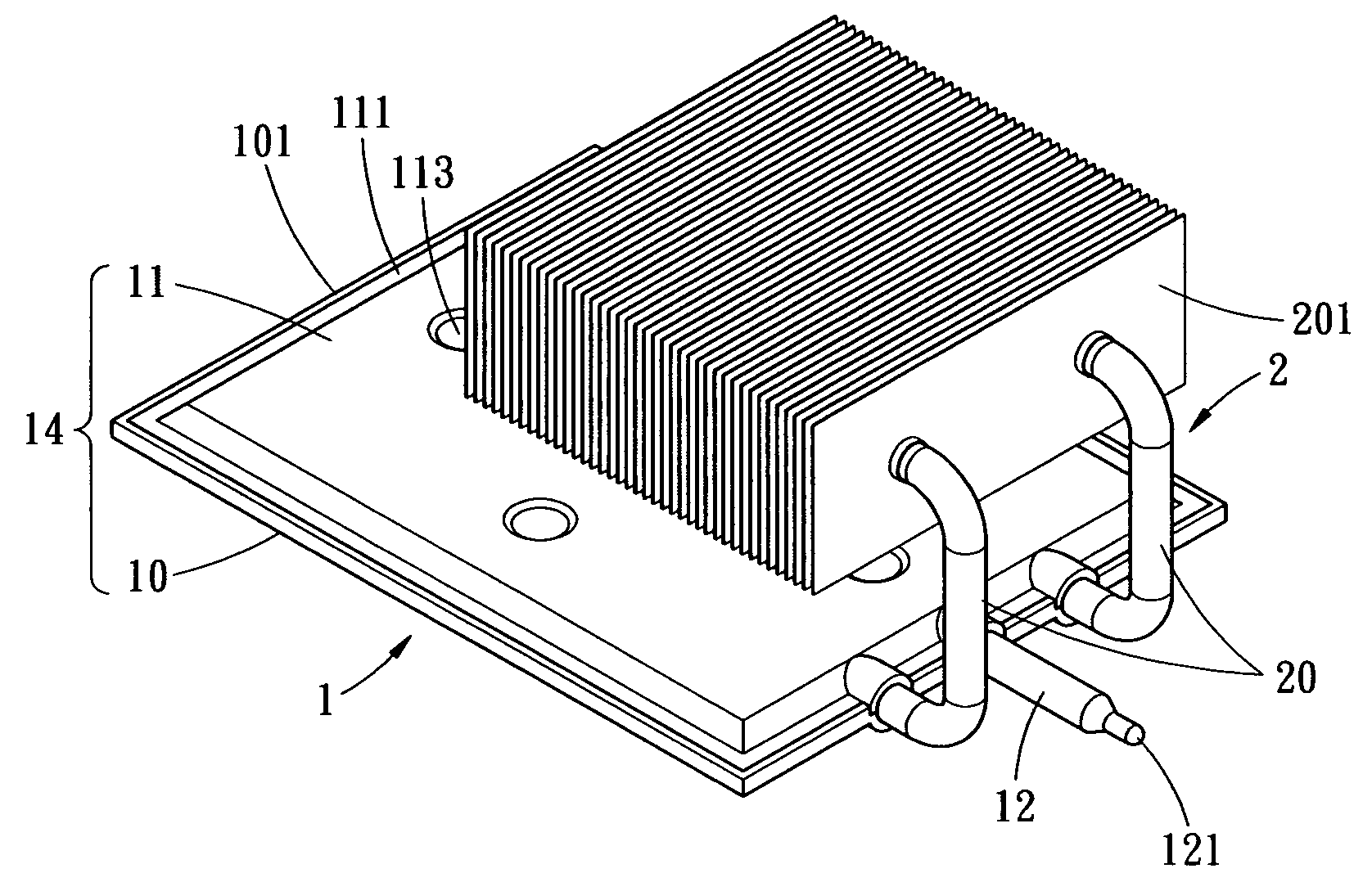
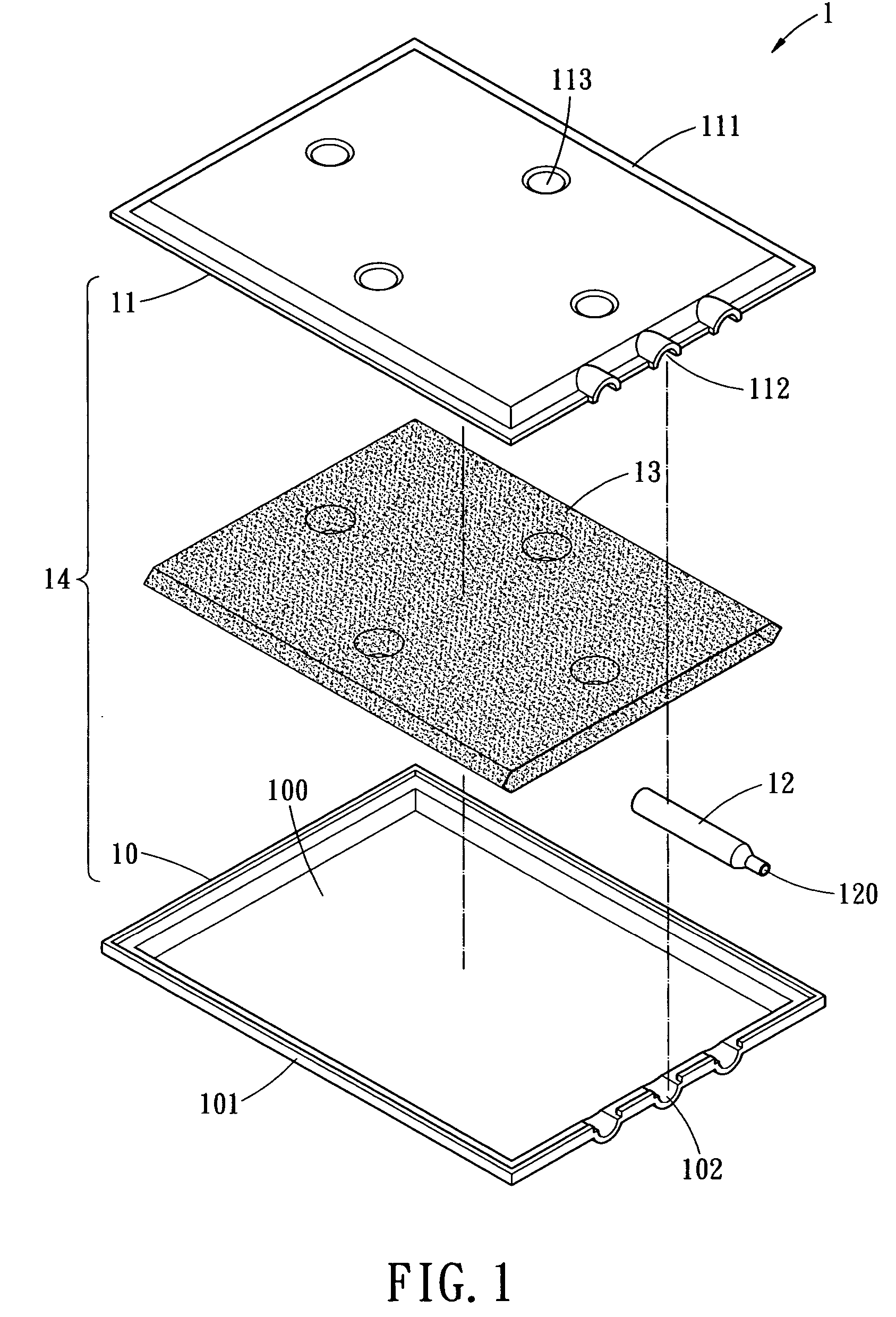
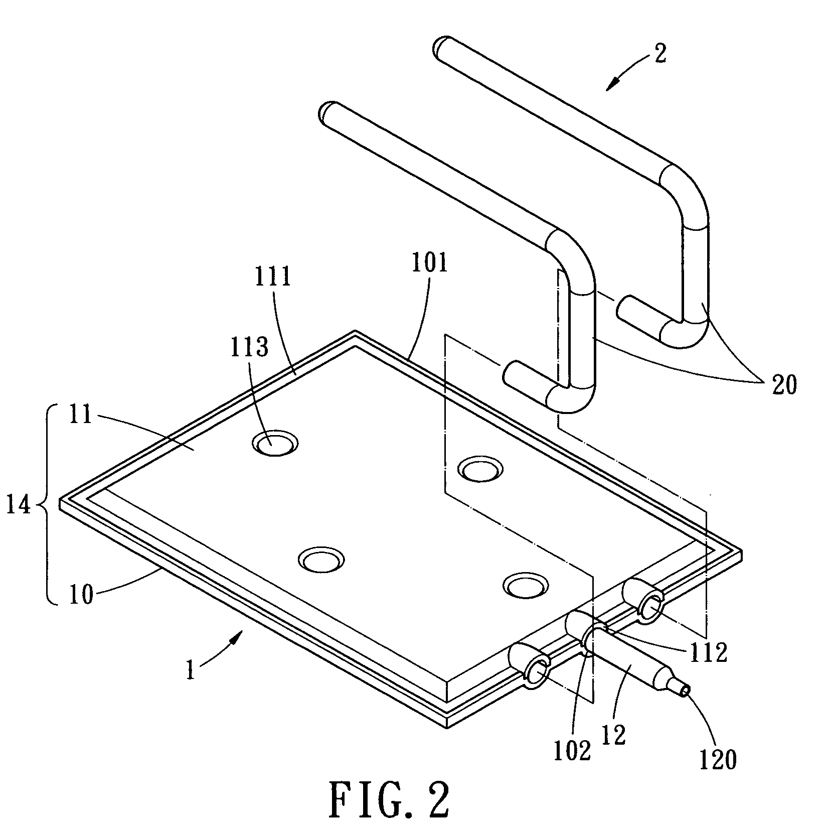
[0019] As shown in FIGS. 1 to 3, an exploded of a heat sink body, an exploded view and a perspective view of a structure for expanding thermal conducting performance of the heat sink are illustrated. The structure includes a thermal expansion conductor 2 embedded in the heat sink 1. The thermal expansion conductor 2 has good thermal conducting efficiency. The thermal expansion conductor 2 is hollow and is in fluid communication with an internal space of the heat sink 1. Therefore, the thermal expansion conductor 2 serves as an extension of the heat 1 for thermal conduction. By the thermal expansion conductor 2, heat is absorbed and dissipated away from the heat sink, or conducted and delivered to a...


PUM


Abstract

A structure for expanding thermal conducting performance of a heat sink includes a bottom plate, a top plate, a hollow filling tube, a wick structure and a hollow thermal expansion conductor. The top and bottom plates are covered with each other to form a planar shell, in which an upper receiving chamber and a lower receiving chamber are formed. The wick structure is attached to the planar shell in upper and lower receiving chambers. The filling tube is filled with a working fluid. The thermal conductor has good conducting performance and is embedded in the planar shell. Further, the thermal conductor is in fluid communication with the upper and the lower chamber, such that the thermal conductor can serve as an extension of the planar shell for heat dissipation.

Description

BACKGROUND OF THE INVENTION [0001] The present invention relates in general to a structure for expanding thermal conducting performance of a heat sink; and more particularly, to a heat sink with improved thermal conductivity. [0002] The conventional heat sink includes a bottom plate and a top plate covered with each other to form a planar enclosure. A wick structure is installed inside of the planar enclosure. A working fluid the introduced into the planar enclosure. The planar structure is exhausted and sealed to form a heat sink. [0003] As the conventional heat sink is in the form of a planar structure which delivers heat from the bottom to the top thereof, fins or tubular heat pipe are typically used to aid in heat dissipation. However, though the fins can be integrally formed on the heat sink, the heat dissipation effect on the fins is restricted by the material characteristics thereof. The heat pipe is normally connected to the heat sink by solder, which often obstructs the hea...

Claims


Application Information

Patent Timeline
Patent Type & Authority Applications(United States)
IPC IPC(8): F28D15/02H01L23/427
CPCF28D15/0233H01L23/427H01L2924/0002H01L2924/00
Inventor MENG-CHENG, HUANGWEN - HAE, TSENGWANG, TONY
Owner CHAUN CHOUNG TECH
Why Eureka
Try Eureka