
Method and apparatus for an oval carbonator

a carbonator and apparatus technology, applied in the field of beverage dispensing, can solve the problems of increasing the size of the cold plate, affecting the quality of the finished drink, and unable to maximize the size of the carbonator, so as to reduce the amount of material required, increase the exterior surface area, and reduce the height

Active Publication Date: 2005-08-18
LANCER PARTNERSHIP
View PDF16 Cites 0 Cited by
  • Summary
  • Abstract
  • Description
  • Claims
  • Application Information

AI Technical Summary

Benefits of technology

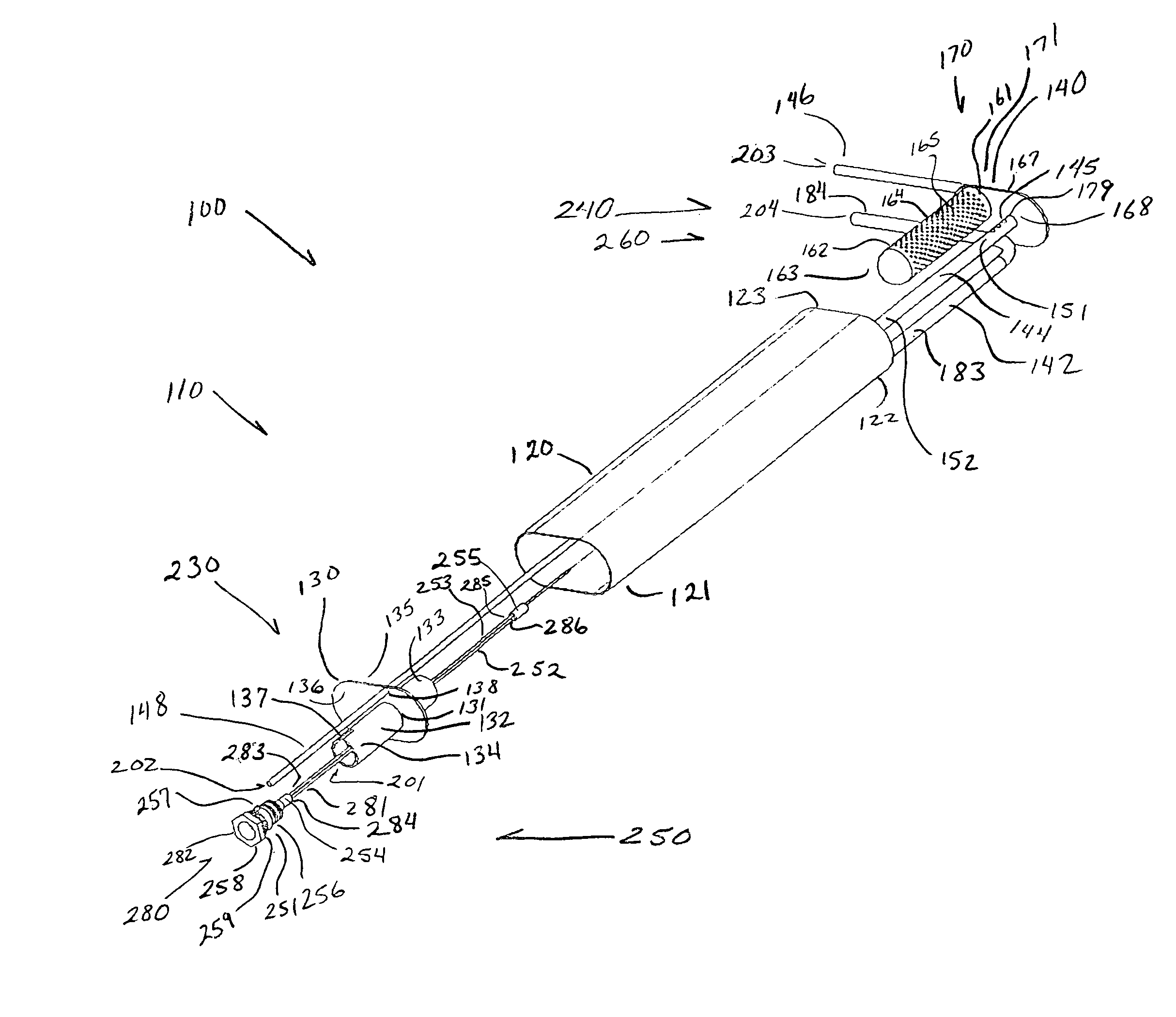
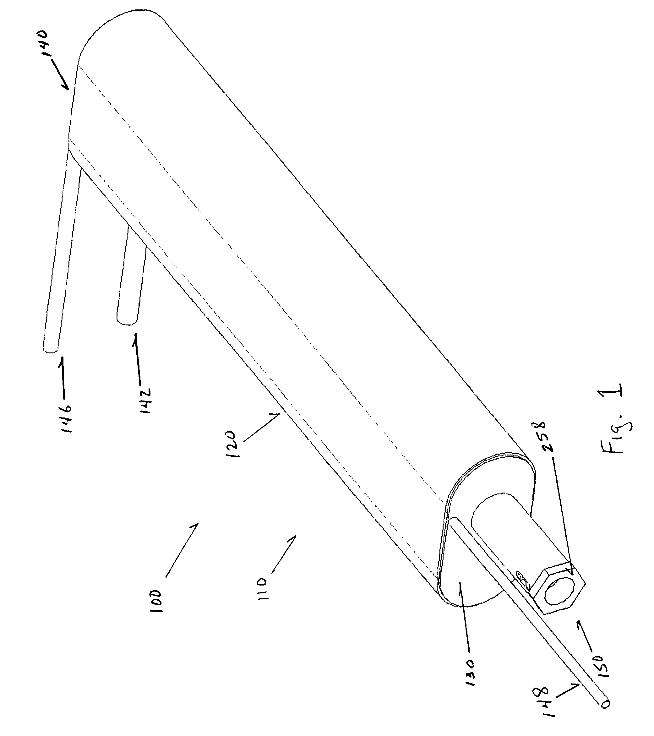
[0009] In accordance with the present invention, an oval carbonator provides a decreased height and an increased exterior surface area for carbonators. The decreased height reduces the amount of material required in a cold plate, while the increased exterior surface area provides additional heat removal capability. The oval shape further provides an increased liquid / gas interaction area. The oval carbonator further consolidates carbonator components into a single location, therein simplifying tubing runs in an associated cold plate, and reducing manufacturing costs.
[0010] The invention further includes a film generator assembly for increasing the surface area of a liquid stream for interaction with a gas. A corresponding method increases the amount of liquid surface area present in the carbonator. The film generator assembly further isolates the incoming liquid and the turbulence associated with the incoming liquid to provide an improved level sensing capability.
[0011] It is therefore an object of the present invention to provide a carbonator with an oblong shell for a decreased carbonator height.

Problems solved by technology

Unfortunately, carbonation of a beverage can dramatically affect the quality of a finished drink.
While cast-in-place carbonators provide increased efficiencies, it is often a struggle to maximize the size of the carbonator, without increasing the size of the cold plate.
Further complications arise when the multitude of preformed dispensing tubes located in the cold plate must be adjusted to provide clearance for the integral carbonator.
Attempts have been made to reduce the height of the carbonator, but have resulted in complex designs that are difficult to manufacture.

Method used


Image

  • Method and apparatus for an oval carbonator
  • Method and apparatus for an oval carbonator
  • Method and apparatus for an oval carbonator

Examples


Embodiment Construction

[0025] As required, detailed embodiments of the present invention are disclosed herein; however, it is to be understood that the disclosed embodiments are merely exemplary of the invention, which may be embodied in various forms. It is further to be understood that the figures are not necessarily to scale, and some features may be exaggerated to show details of particular components or steps.

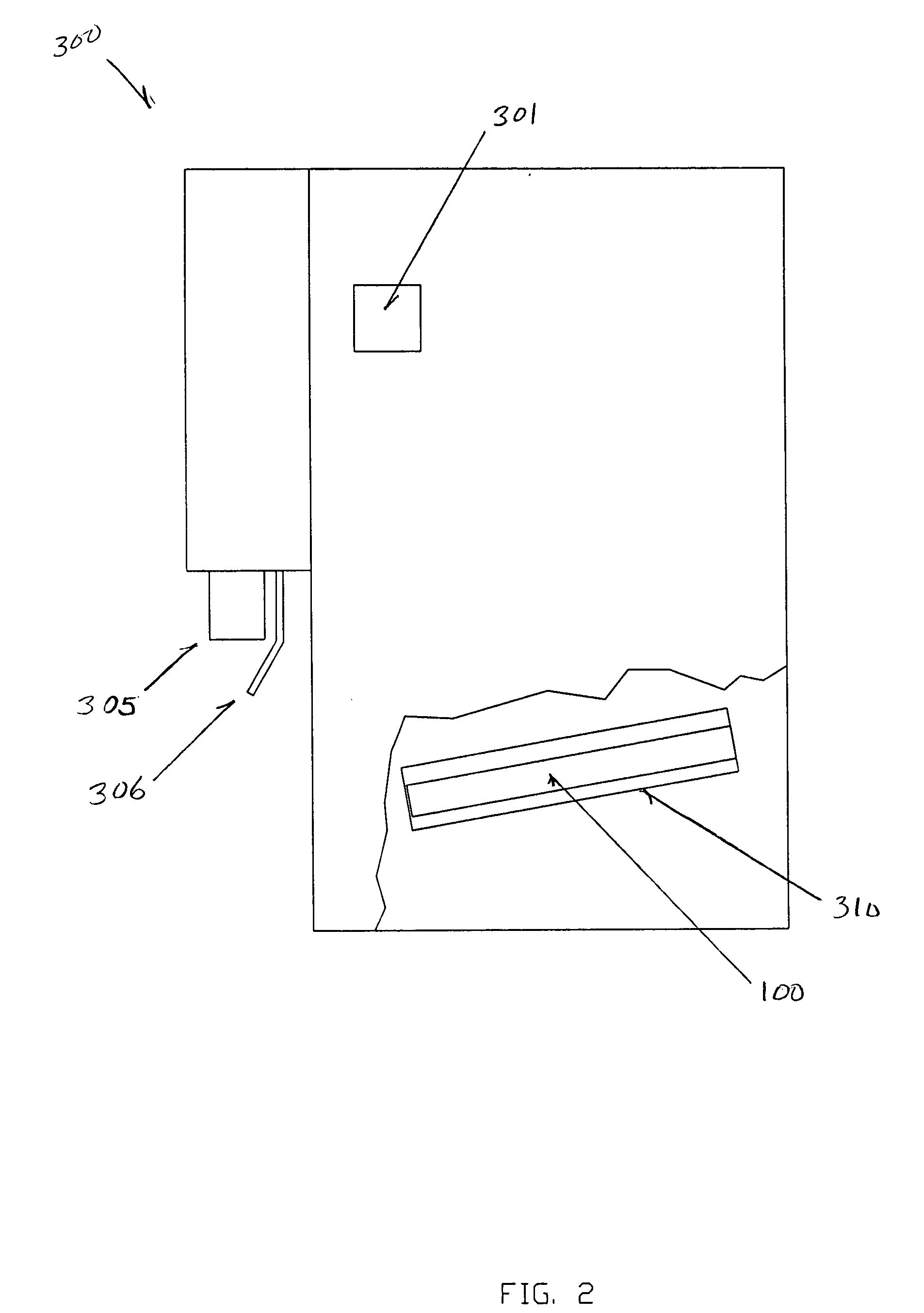
[0026] An oval carbonator minimizes the height required in a cold plate and increases the gas / water interaction area in the carbonator as compared to commonly used circular carbonator designs. The oval carbonator further includes a film generator assembly that more efficiently diffuses the incoming water, thereby promoting increased surface area exposure for interaction with gas in the carbonator. The oval carbonator includes a probe that may be used with a controller to ascertain whether the carbonator requires refilling. The oval carbonator is designed to be used in a cold plate of a beverage...


PUM

PropertyMeasurementUnit
angleaaaaaaaaaa
pressureaaaaaaaaaa
surface areaaaaaaaaaaa

Abstract

A method and corresponding apparatus for an oval carbonator employ an oblong housing to provide an improved gas / water interaction area within the confines of the carbonator. The increased cross sectional area provides a larger water surface area, whereby an increased amount of the pressurized gas is exposed to the increased surface area. Further advantages of the oval carbonator include a simplification of the tubing bundles that are cast into the cold plate. The oval carbonator consolidates the volumes previously used by the carbonator, thereby allowing the tubing bundles to be consolidated. Consolidation of this type translates into reduced manufacturing time and increased savings due to the simplified design.

Description

BACKGROUND OF THE INVENTION [0001] 1. Field of the Invention [0002] The present invention relates to beverage dispensing and, more particularly, but not by way of limitation, to methods and apparatus for beverage dispensing with cold carbonation. [0003] 2. Description of the Related Art [0004] In the post-mix beverage dispensing industry, carbonated beverages account for the largest segment of the different beverage types. Unfortunately, carbonation of a beverage can dramatically affect the quality of a finished drink. Proper carbonation must be achieved in order to consistently produce quality drinks, including minimal foaming. [0005] Over the past decades, it has been determined that colder temperatures in the carbonation process produce better carbonation efficiencies and can be accomplished at lower carbon dioxide pressures. As such, the carbonation methods used to carbonate finished drinks have moved from ambient carbonators to various forms of chilled carbonators. A further de...

Claims


Application Information

Patent Timeline
Patent Type & Authority Applications(United States)
IPC IPC(8): A23L2/54B01F3/04B67D1/00
CPCA23L2/54B01F3/04049B01F3/04808B01F2003/04893Y10S261/07B01F2215/0022B01F2215/0052B67D1/0057B67D1/0073B01F2003/049B01F23/2132B01F23/23762B01F23/237621B01F23/2362B01F2101/14B01F2101/305
Inventor ROMANYSZYN, ADRIAN M.
Owner LANCER PARTNERSHIP
Learn More