Cylindrical vibration damping apparatus and method of manufacturing the same

a technology of cylindrical rollers and damping devices, which is applied in the direction of mechanical devices, shock absorbers, machine supports, etc., can solve the problems of inability to distinguish the front and back of the rubber stop plate, the likelihood of drawbacks, and the significant amount of extra labor, and achieve excellent production efficiency

Inactive Publication Date: 2005-08-18
SUMITOMO RIKO CO LTD
View PDF5 Cites 6 Cited by
  • Summary
  • Abstract
  • Description
  • Claims
  • Application Information

AI Technical Summary

Benefits of technology

[0034] As will be apparent from the description hereinabove, according to the cylindrical vibration damping apparatus constructed in accordance with the invention and the cylindrical vibration damping apparatus manufacturing method in accordance with the invention, the use of an extremely simple arrangement, namely, forming three or more mating recesses/protrusions on the outer circumferential surfaces of the two ends of the inner shaft member and on the inner circumferential surfaces of mount holes in a pair of rubber stop plates, makes it possible to a

Problems solved by technology

In view of recent deliberations regarding shipping components with the bracket attached, in the event that the rubber stop plate were found to be improperly installed during inspection after the bracket has been attached, it would be necessary to remove the bracket in order to perform the repair operation, resulting in the significant problem of a considerable amount of extra labor.
However, in the cylindrical vibrati

Method used


Image

  • Cylindrical vibration damping apparatus and method of manufacturing the same
  • Cylindrical vibration damping apparatus and method of manufacturing the same
  • Cylindrical vibration damping apparatus and method of manufacturing the same

Examples


Embodiment Construction

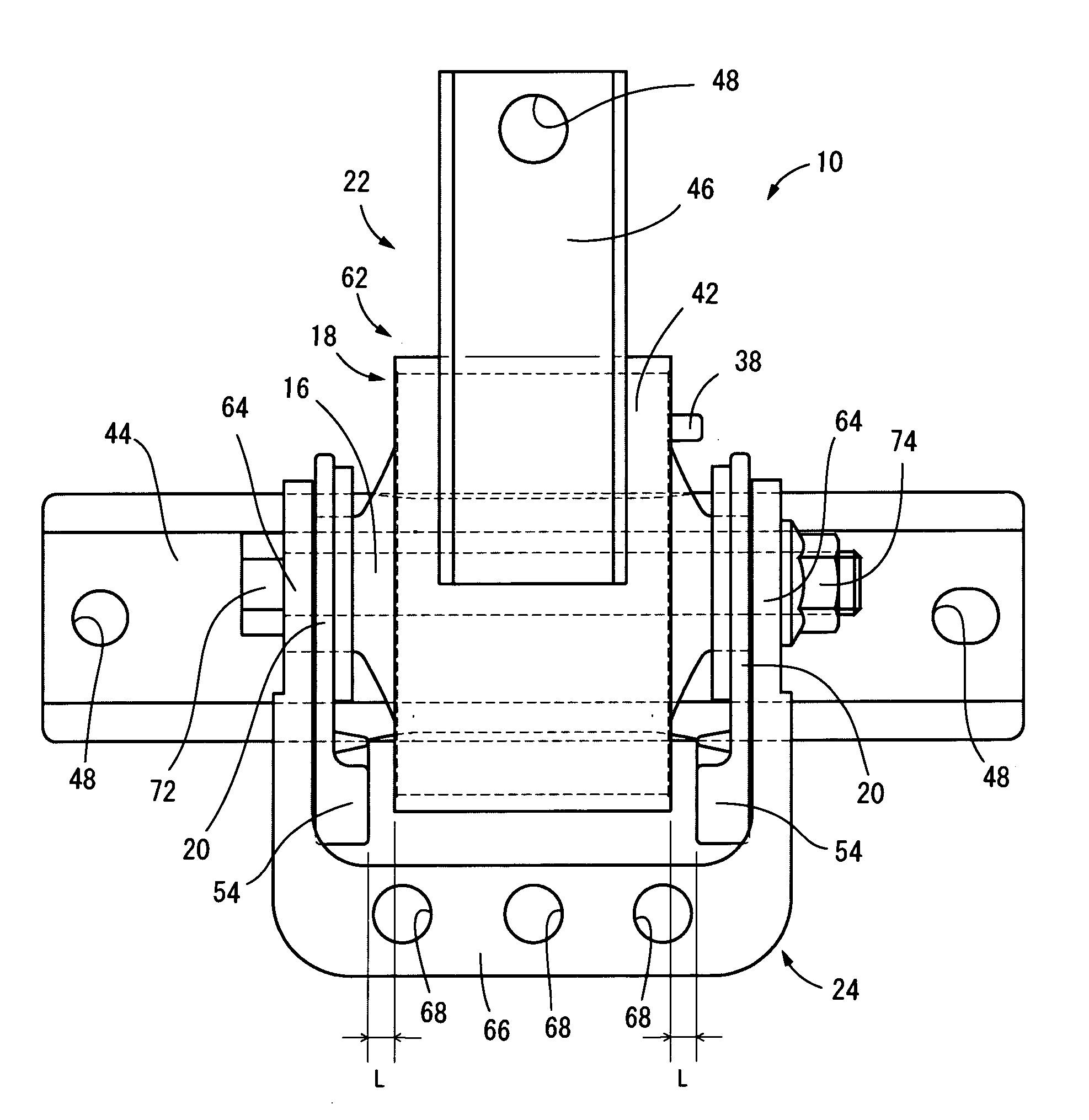
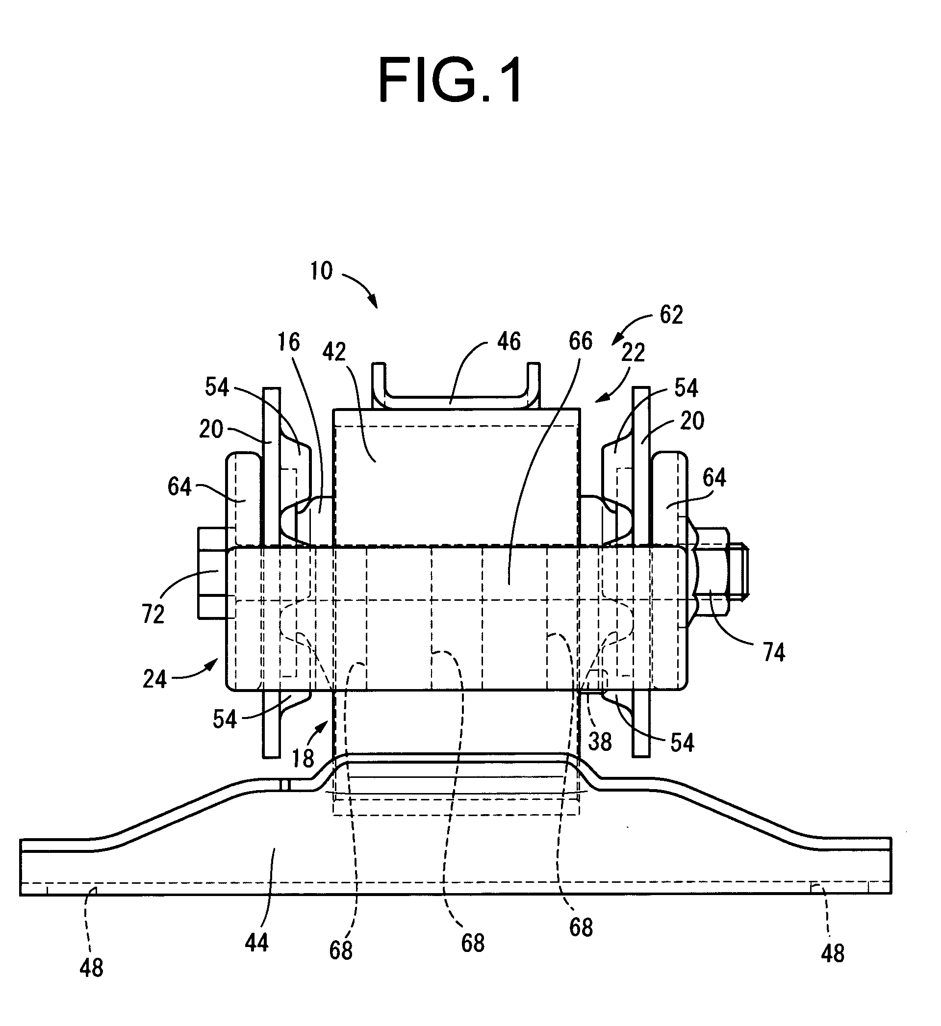
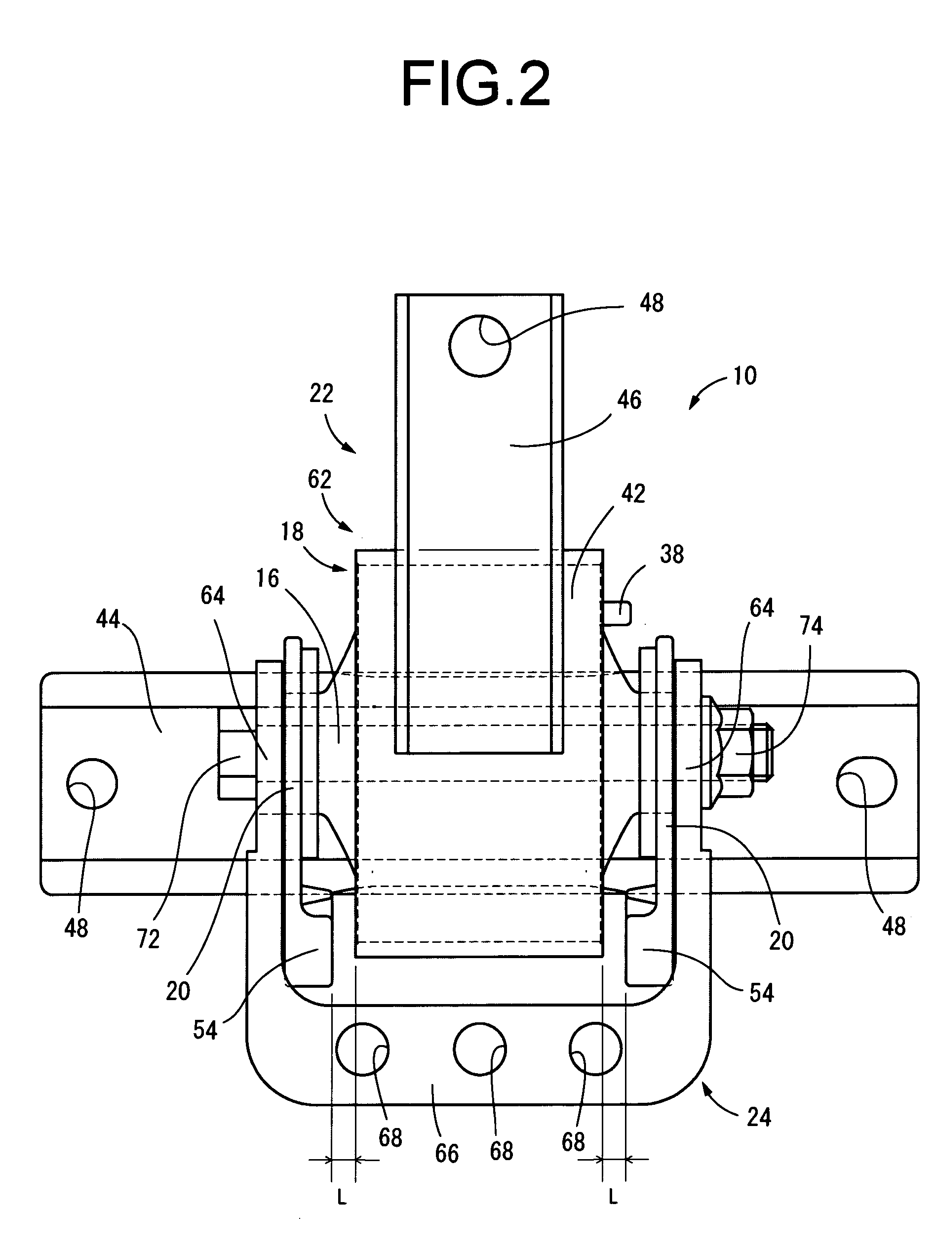
[0060] Referring first to FIGS. 1-3, there is shown by way of a first embodiment of a cylindrical vibration damping apparatus of the invention, i.e., a torque roll mount 10, which is shown as-shipped from the factory. The torque roll mount 10 comprises a mount body 18 which is a cylindrical vibration damping unit having a structure in which an inner shaft member in the form of a metallic inner sleeve 12 and an outer cylindrical member in the form of a metallic outer sleeve 14, are elastically connected by means of a rubber elastic body 16. A pair of rubber stop plates 20, 20 are attached to the mount body 18, at the two axial sides thereof (hereinafter also referred to as the left and right sides). Also, an outer bracket 22 is attached to the outer sleeve 14 and an inner bracket 24 is attached to the inner sleeve 12.

[0061] The torque roll mount 10, oriented with its generally plumb vertical direction coincident with the vertical direction in FIGS. 1 and 3 and the generally front-ba...


PUM


Abstract

A cylindrical vibration damping apparatus having an elastic body connecting an inner shaft and an outer cylinder member, and a pair of rubber stop plates disposed at axial ends of the inner shaft member. Each rubber stop plate has a mount hole that fits about the outside of the inner shaft member. Pairs of mating projections and mating recesses are provided to an interface between an inner circumferential surface of the mount hole of the each rubber stop plate and an outer circumferential surface of the corresponding axial end of the inner shaft member at three or more different intervals in a circumferential direction so that the pair of rubber stop plates are installed onto the axial ends of the inner shaft member with correct identification of a front and back and a circumferential position about the inner shaft member. A method of manufacturing the same is also disclosed.

Description

[0001] The disclosure of Japanese Patent Application No. 2004-040478 filed on Feb. 17, 2004 and No. 2004-347320 fined on Nov. 30, 2004, each including the specification, drawings and abstract is incorporated herein by reference in its entirety. BACKGROUND OF THE INVENTION [0002] 1. Field of the Invention [0003] The present invention relates to a cylindrical vibration damping apparatus favorable for use as an automotive engine mount or torque roll mount, for example, and more particular to a cylindrical vibration damping apparatus equipped with a rubber stop plate constituting a stopper mechanism in the axial direction. [0004] 2. Description of the Related Art [0005] As one type of vibration damping apparatus known in the art for installation between parts that make up a vibration transmitting system, there is known a cylindrical vibration damping apparatus comprising a vibration damping unit of cylindrical shape, having a metallic outer cylindrical member disposed spaced apart to th...

Claims


Application Information

Patent Timeline
IPC IPC(8): F16F13/08F16F1/38F16F3/087F16F5/00F16F13/14F16F13/16F16F15/08
CPCF16F1/3842F16F2230/0047F16F3/0873
Inventor OKANAKA, TAKEHIROHASHIMOTO, FUMIAKI
Owner SUMITOMO RIKO CO LTD
Why Eureka
Try Eureka