

Machining jig
- Summary
- Abstract
- Description
- Claims
- Application Information
AI Technical Summary
Benefits of technology
Problems solved by technology
Method used
Image

Examples
Embodiment Construction
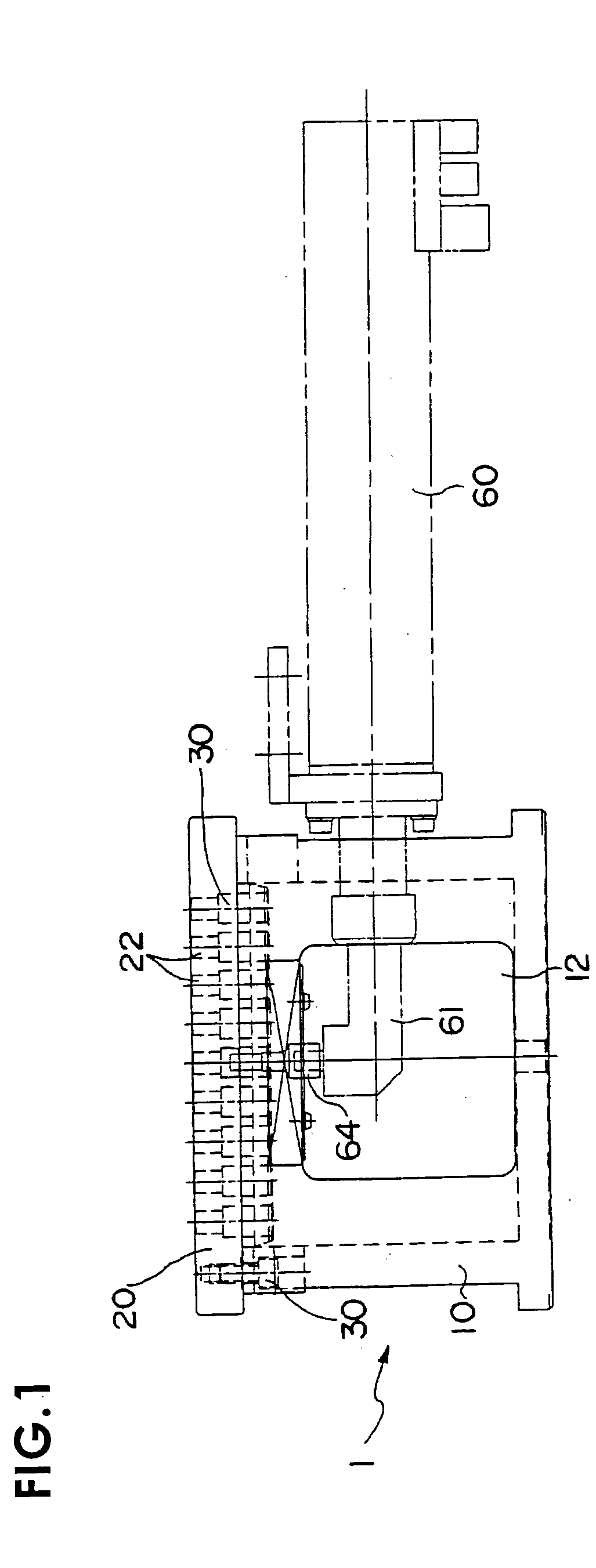
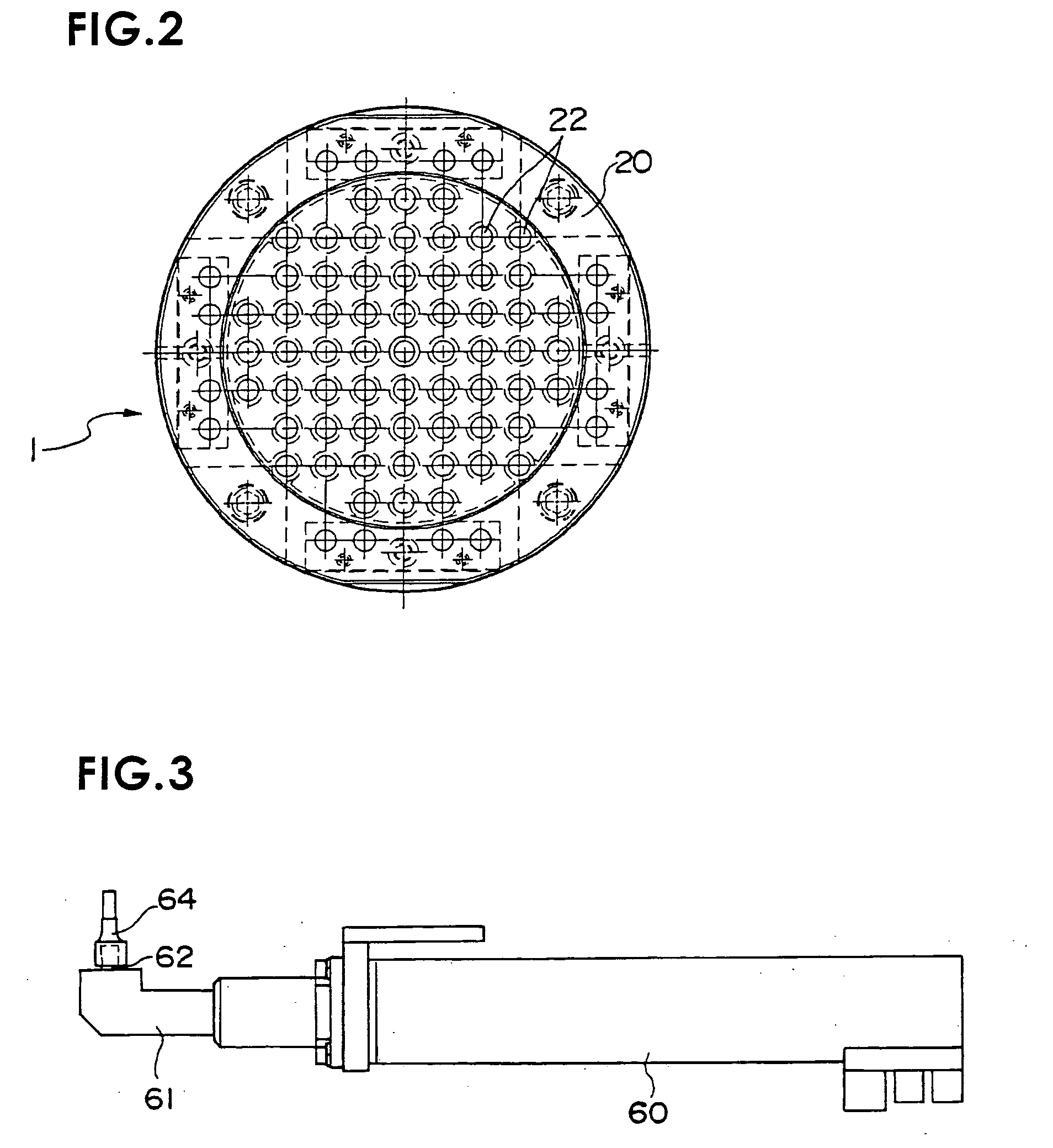
[0029]FIG. 1 is a front view of a jig base and a pallet according to the machining jig of the present invention, and FIG. 2 is a plan view thereof.
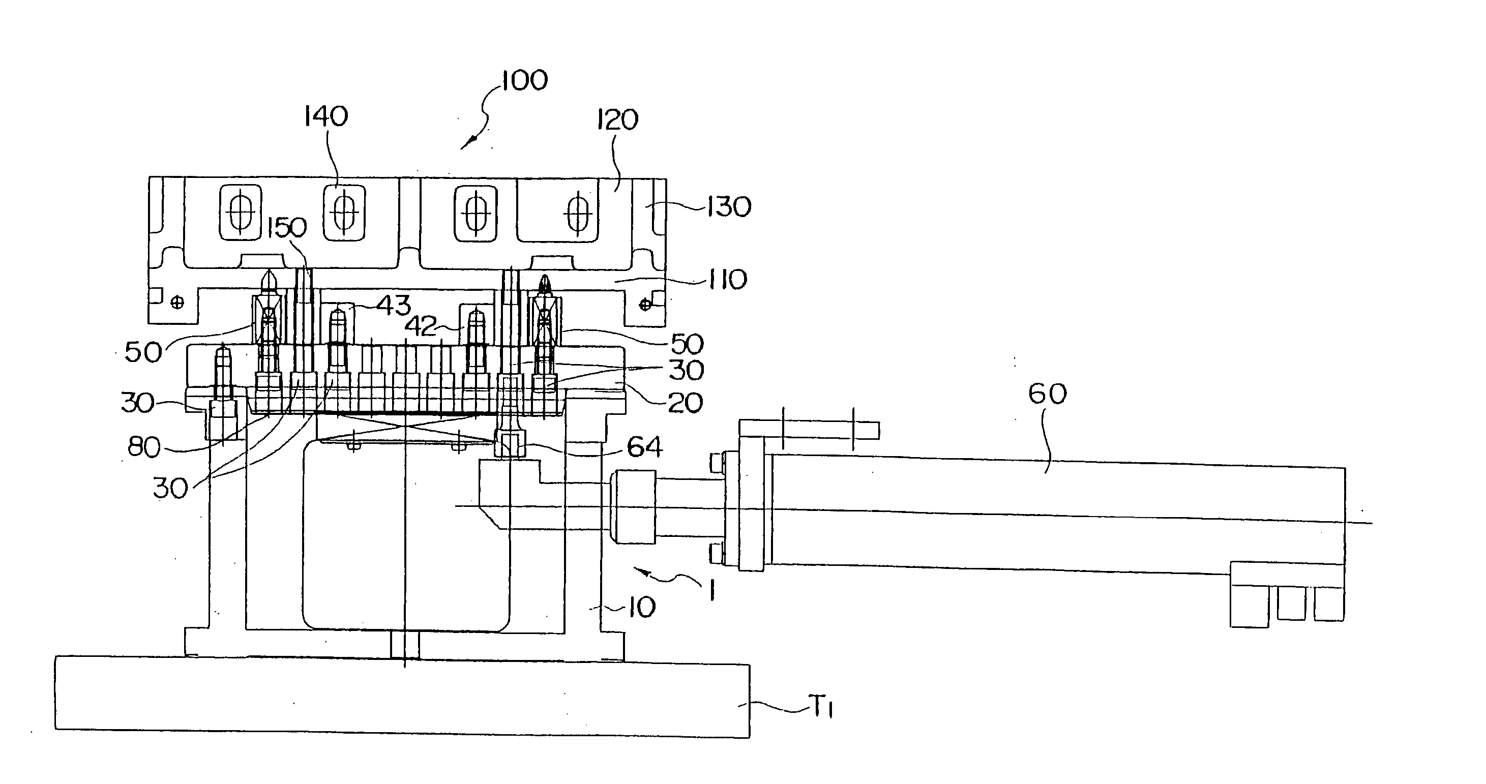
[0030] The machining jig, the whole of which being denoted by reference number 1, is composed of a jig base 10 and a pallet 20, and the pallet 20 is fixed to the jig base 10 by bolts 30.
[0031] A large number of bolt holes 22 are formed to the pallet 20 at predetermined intervals, and each bolt hole has a bolt 30 inserted upward thereto. On the back side of the pallet 20, there is attached a plate with holes for preventing the bolts 30 screwed onto the bolt holes 22 from falling.
[0032] The jig base 10 has openings 12 formed on four sides thereof, and through these openings 12, a head 61 of a bolt runner 60 attached to a robot arm is inserted to manipulate the bolts 30 within the pallet 20.
[0033]FIG. 3 is a front view of the bolt runner, and FIG. 4 is a plan view thereof.
[0034] The bolt runner 60 has a drive device disposed in the inte...
PUM
 Abstract
Description
Claims
Application Information