Angled reaction vessel

Inactive Publication Date: 2007-08-16
BIOMASS WORLDWIDE GROUP
View PDF99 Cites 42 Cited by
  • Summary
  • Abstract
  • Description
  • Claims
  • Application Information

AI Technical Summary

Benefits of technology

[0024] The biomass bearing material treatment vessel includes a swing-away door assembly, which is adjacent the access opening. The door assembly includes a swing-away door, which covers the access opening, and a davit assembly for supporting the swing-away door. The davit assembly includes a generally vertical davit upright, which supports the door through a generally horizontal door support arm. The support arm has a first end and a second end with a counterweight attached to the first end and the access opening door attached to the second end. The davit assembly is configured to rotate around the davit upright so the access opening door may be rotated away from or toward the access opening. This can be accomplished by manual rotation of the davit assembly or it can easily be automated.
[0025]

Problems solved by technology

Handling solid waste is an increasingly difficult problem in the industrialized nations.
However, nationwide the number of solid waste landfills is falling as the landfills fill to capacity and close, while new landfills cannot be opened due to regulations.
Some ex

Method used


Image

  • Angled reaction vessel
  • Angled reaction vessel
  • Angled reaction vessel

Examples


Example

[0048] While the invention is susceptible of various modifications and alternative constructions, certain illustrated embodiments thereof have been shown in the drawings and will be described below in detail. It should be understood, however, that there is no intention to limit the invention to the specific form disclosed, but, on the contrary, the invention is to cover all modifications, alternative constructions, and equivalents falling within the spirit and scope of the invention as defined in the claims.

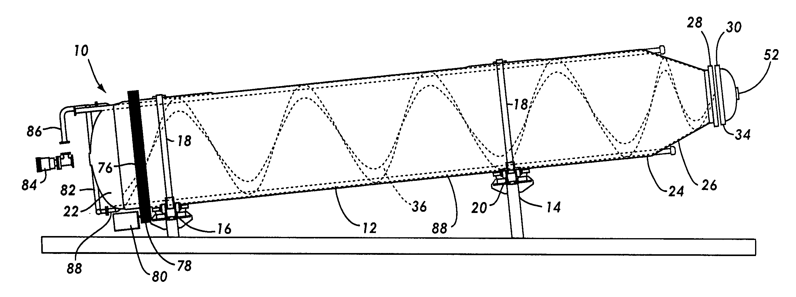
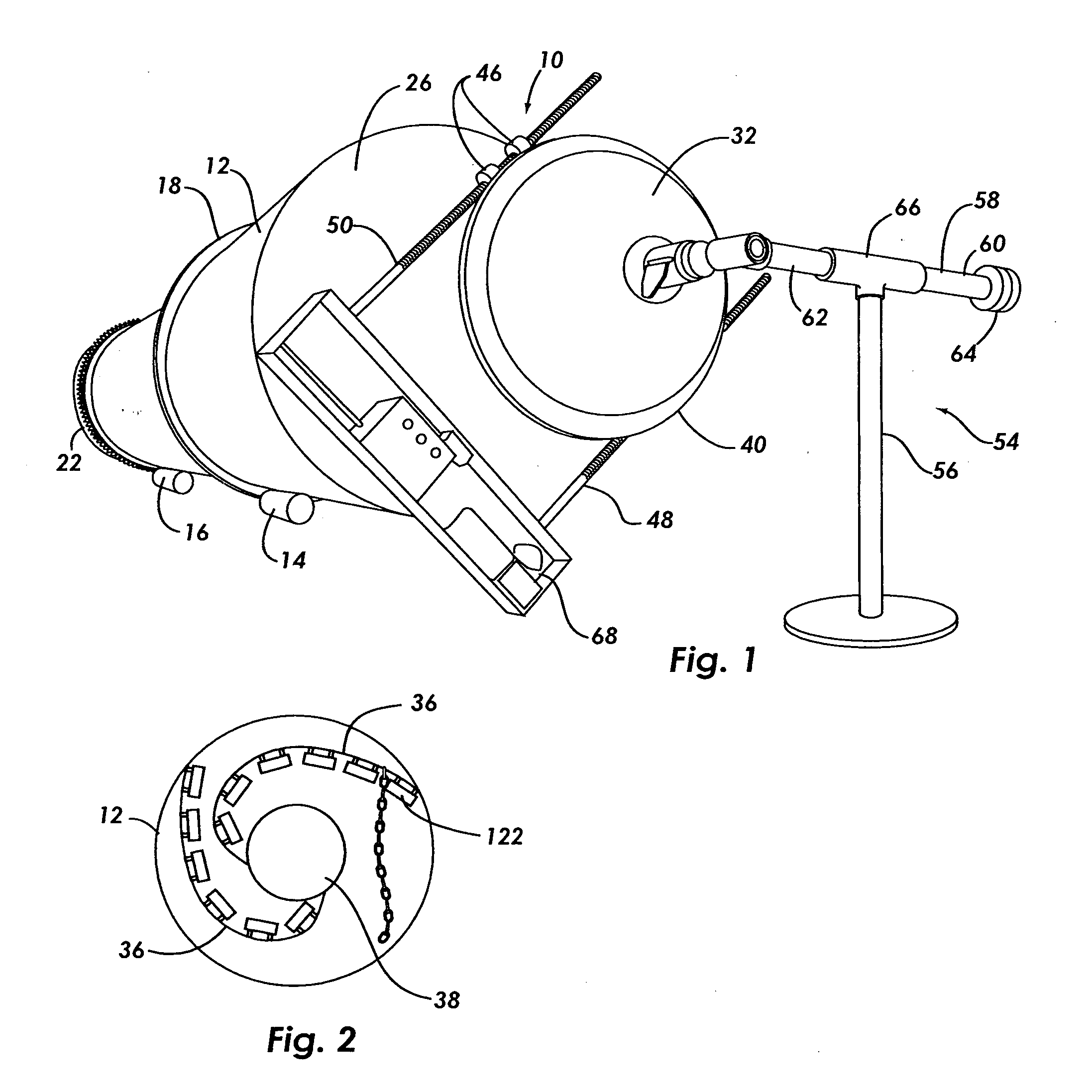
[0049] Some of the preferred embodiments are shown in the FIGS. 1 through 12. FIG. 1 shows the biomass bearing material treatment vessel 10. It includes a reaction vessel 12. In one preferred mode of the invention, a first trunnion assembly 14 and a second trunnion assembly 16 supports the reaction vessel 12. The trunnion assembly includes a track 18 and a trunnion 20. These components can be sized according to the size of a specific reaction vessel. However, in a preferred embo...


PUM


Abstract

The invention is an apparatus and a process for treating biomass bearing material including municipal solid waste (MSW). The apparatus includes a reaction vessel held at an angle and configured for rotation and steam injection, with helically arranged internal flights, a self-aligning door closure, and a swing-away door assembly. It also includes a novel structure for shredding biomass bearing material attached to the edges of the flights. This structure is a number of projecting tooth like points and paddles.

Description

FIELD OF THE INVENTION [0001] The present invention generally relates to processing biomass bearing material including municipal solid waste (MSW), and more particularly relates to reaction vessels for treating biomass bearing material and other material containing cellulose or biomass in a heated and pressurized process. BACKGROUND OF THE INVENTION [0002] Handling solid waste is an increasingly difficult problem in the industrialized nations. Sixty-one percent of the United States' solid waste is dependent on disposal in landfills. However, nationwide the number of solid waste landfills is falling as the landfills fill to capacity and close, while new landfills cannot be opened due to regulations. The national average for solid waste disposal fees has increased by about 400 percent since 1985. Such fees, called tipping fees, can be expected to raise an average of seven percent per year. In addition, the number of solid waste transfer stations has increased due to the closure of man...

Claims


Application Information

Patent Timeline
IPC IPC(8): C12M1/02
CPCB01J2219/187B01J2219/1943C12M23/38C12M23/50F26B2200/02C12M29/06F26B11/0468F26B11/0477C12M27/10
Inventor NOLL, ANTHONY P.
Owner BIOMASS WORLDWIDE GROUP
Why Eureka
Try Eureka