Boat trailer

a boat trailer and trailer technology, applied in the field of trailers, can solve the problems of ineffective tightening of the nuts and the inventor's technical difficulties, and achieve the effects of increasing the safety of the trailer, reducing the inventory, and little or no cos

Inactive Publication Date: 2005-08-18
ROBERTS JR RONALD E
View PDF13 Cites 5 Cited by
  • Summary
  • Abstract
  • Description
  • Claims
  • Application Information

AI Technical Summary

Benefits of technology

[0016] In a preferred embodiment, the invention may implement a safe edge on the fenders of the trailer. The inventor overcame the danger caused by the razor sharp edge of the fender by cold-rolling the edge of the fender. Through the novel use of this process during the manufacture of a trailer, the cold-rolling eliminates the sharp edge of the fender, thereby increasing the safety of the trailer at little or no cost to the manufacturer. A further embodiment of this invention implements the safe edge on various other edges of the trailer.
[0017] In the present invention; the front and trailing hangers are identical. While the front leaf spring eye is attached in the same method as taught previously, the trailing leaf spring eye can be attached to the trailing hanger via the use of offset shackles to make the transition from 2¾″ (outside dimension of hanger) to the 1¾″ inside dimension of the trailing leaf spring eye. Thus, one advantage of standardizing the hanger dimensions is that the manufacturers can reduce their inventory by only having to stock one type of hangers through the use of the offset shackle.
[0018] In a preferred embodiment, the invention can provide a mount for a clearance light in the fender steps. The inventor was able to avoid the necessity of welding or riveting the fender step on a mounting point. In this embodiment of the invention, the light mounting point does not require any welding or other assembly. By forming the light under the step, the light can be protected.
[0019] In a preferred embodiment, the invention can cap the end of the I-beam with a light bracket. In a preferred embodiment, the light bracket is substantially S-shaped. The light bracket can have at least one vertical section and at least horizontal section. At least one horizontal surface of the light bracket can be suitable for attachment to the bottom surface of the I-beam and the top surface of the cross bar member. The same hole pattern that is used on the cross bar member can be stamped into the light bracket, which eliminates the need for any additional holes in order to mount the bracket. Then, the bracket can be placed between the top surface of the trailing cross bar member and the bottom surface of the I-beam. Finally, the bracket can be secured with bolts.
[0020] As described above, methods of production in the prior art consisted of hand drilling and welding. A more technologically advanced manufacturer might use drill presses. However, the concept of punching I-beams, standardizing the hole patterns and designing the various embodiments as described herein has produced a very unique boat trailer assembly. The end result of this invention is a trailer that is superior in quality and aesthetics and that is significantly less expensive to build than conventional methods.

Problems solved by technology

Unfortunately, the decision to use carriage bolts presented additional technical problems that the inventor had to overcome.
For example, when joining the cross bar members to the I-beams, the inside holes of the cross member were not accessible with a wrench, which meant that the nut could not be efficiently tightened.

Method used


Image

  • Boat trailer
  • Boat trailer
  • Boat trailer

Examples


Embodiment Construction

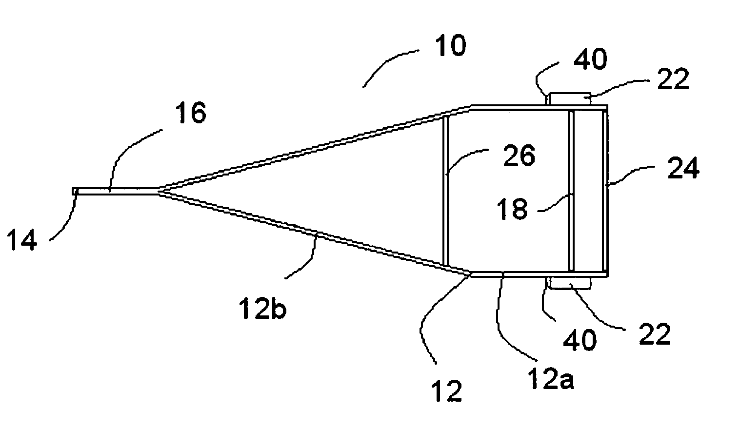
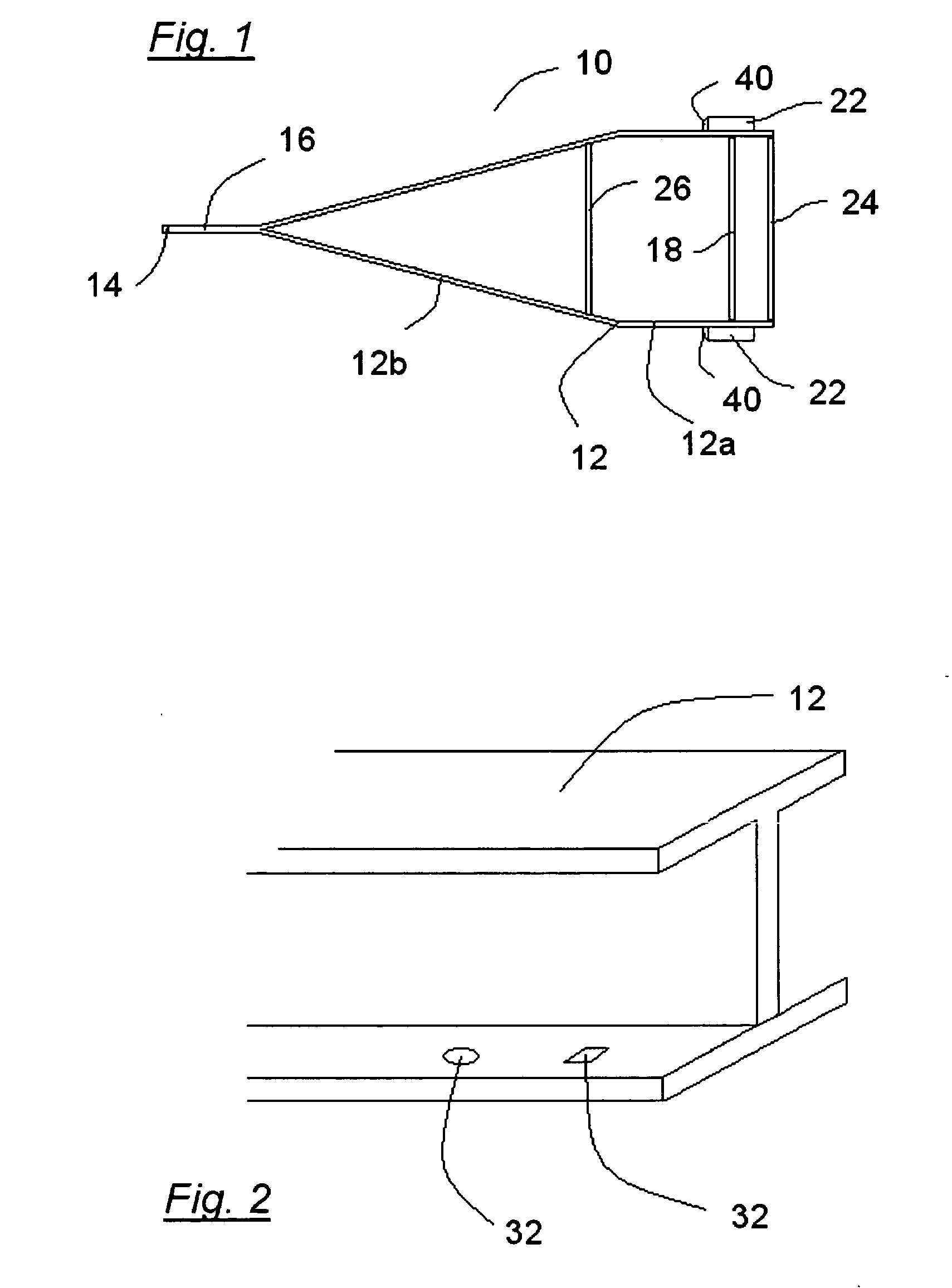
[0032] Referring now to the drawings, various arrangements are illustrated for utilizing the present invention on a boat trailer. However, it is understood that the use of the invention on a boat trailer is a preferred embodiment, for purposes of illustration. The use of the present invention is not intended to be limited to boat trailers. As is known to those skilled in the art and as is depicted in FIG. 1, trailers 10 include a pair of side frame members, or side beams, 12 which have a spaced parallel load-supporting portion 12a, upon which an object is carried, and a forward converging or tongue-forming portion 12b, through which the trailer is connected to a towing vehicle by means of a trailer hitch coupling 14. In a preferred embodiment, the side beams 12 are I-beams and may be formed by aluminum or other suitable materials.

[0033] The trailer 10 also includes an axle 18 and springs (not shown) that may be longitudinally adjustable relative to the side beams 12. Rubber-tired w...


PUM


Abstract

A boat trailer comprising two side beams positioned adjacent to each other, wherein each of the side beams has a forward tongue forming portion converging toward the other side beam. The side beams can be connected to a towing vehicle and the side beams may also have a trailing boat-supporting portion. The trailer also includes at least one cross bar member extending between the boat-supporting portion of one of the side beams and the boat-supporting portion of the other side beam. The various members of the trailer may be punched with holes in a standard pattern.

Description

FIELD OF THE INVENTION [0001] The present invention relates generally to trailers and more specifically to boat trailers, particularly aluminum boat trailers. DESCRIPTION OF THE RELATED ART [0002] Previous boat trailer assembly methods have proven costly, inefficient and dangerous. [0003] Trailers are assembled through the joining of beams and cross-beams. In order to maintain a clean line on the top of the trailer, the prior art taught that the bottom of the beam should be drilled so that the hardware used to connect the various beams would not extend to the surface of the trailer. In the prior art, one skilled in the art of assembling boat trailers would orient the boat trailers upside-down during the assembly process It was deemed advantageous to orient the trailer upside-down so that the assembly personnel could have access to the underside of the various beam members in order to drill the necessary holes. [0004] In order to join the beam members, assembly personnel hand drilled...

Claims


Application Information

Patent Timeline
Patent Type & Authority Applications(United States)
IPC IPC(8): B60P3/10B62D21/20
CPCB62D21/20B60P3/1033
Inventor ROBERTS, RONALD E. JR.
Owner ROBERTS JR RONALD E
Why Eureka
Try Eureka