Vehicle head lamp

a head lamp and vehicle technology, applied in the field of vehicle lamps, can solve problems such as the increase in the cost of vehicle lamps

Active Publication Date: 2005-08-18
KOITO MFG CO LTD
View PDF4 Cites 36 Cited by
  • Summary
  • Abstract
  • Description
  • Claims
  • Application Information

AI Technical Summary

Benefits of technology

[0011] Furthermore, the luminous energy control section may increase the luminous energies of the semiconductor

Problems solved by technology

This has often resulted in an inc

Method used


Image

  • Vehicle head lamp
  • Vehicle head lamp
  • Vehicle head lamp

Examples


Embodiment Construction

[0023] The invention will be described on the basis of the embodiments; however, the embodiments provided below do not limit the scope of the present invention as set forth in the appended claims. In addition, not all the combinations of the features described in the embodiments are indispensable to means for resolution of the invention.

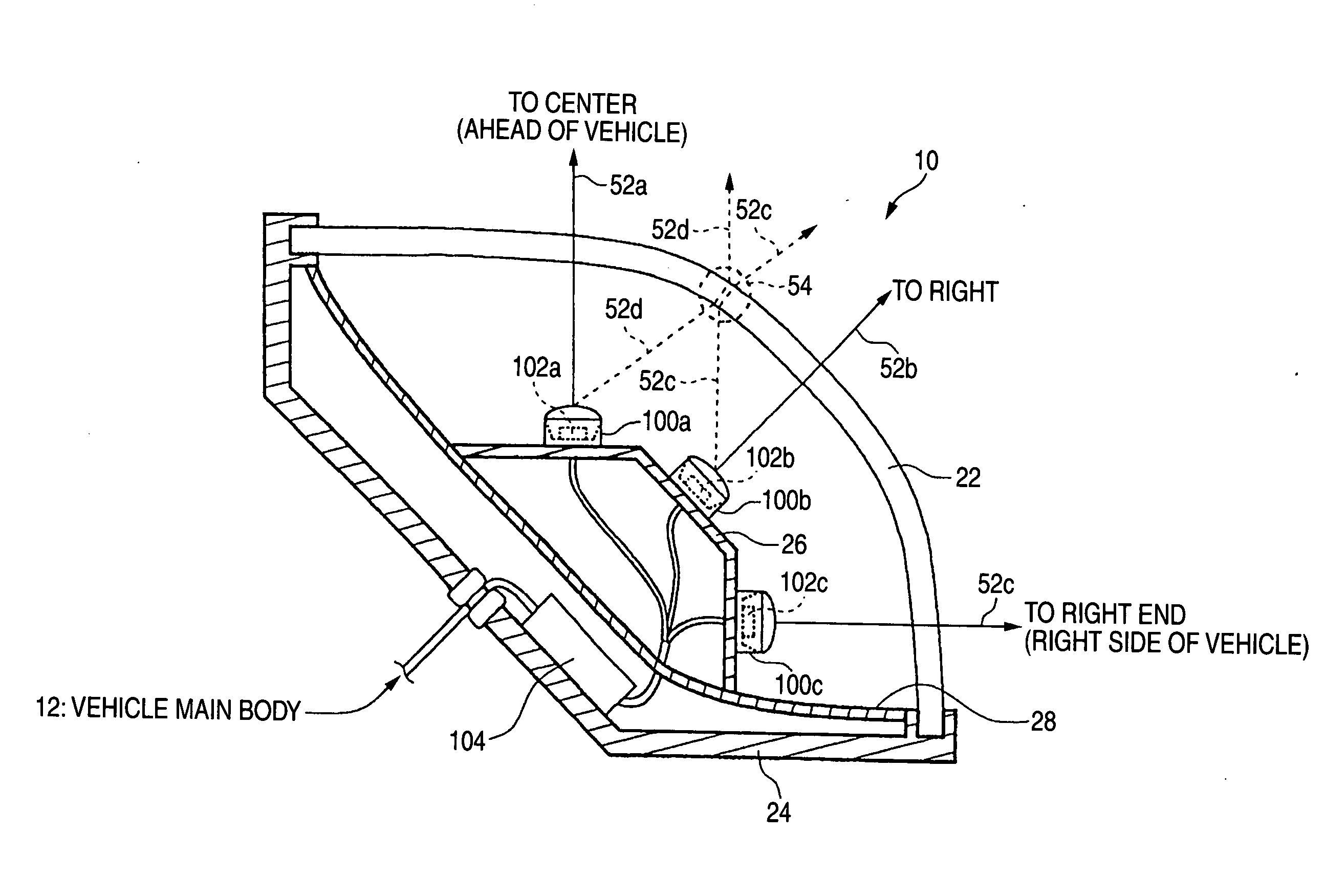
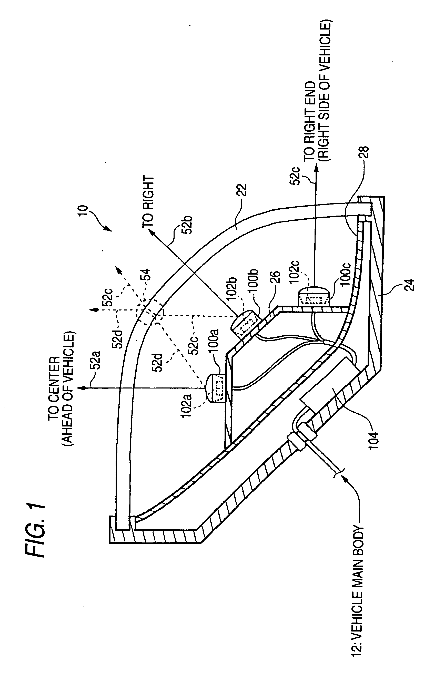
[0024]FIG. 1 is a horizontal cross-sectional view showing an example of the configuration of a vehicle lamp 10 according to an embodiment of the present invention. The embodiment aims at providing the vehicle lamp 10 which can change light distribution at low cost. The vehicle lamp 10 of the embodiment is an additional illumination lamp attached to the right side on the front of a vehicle. The vehicle lamp 10 includes a light source support section 26, a plurality of light source modules 100a to 100c, an outer lens 22, a lamp body 24, an extension reflector 28, and a luminous energy control section 104.

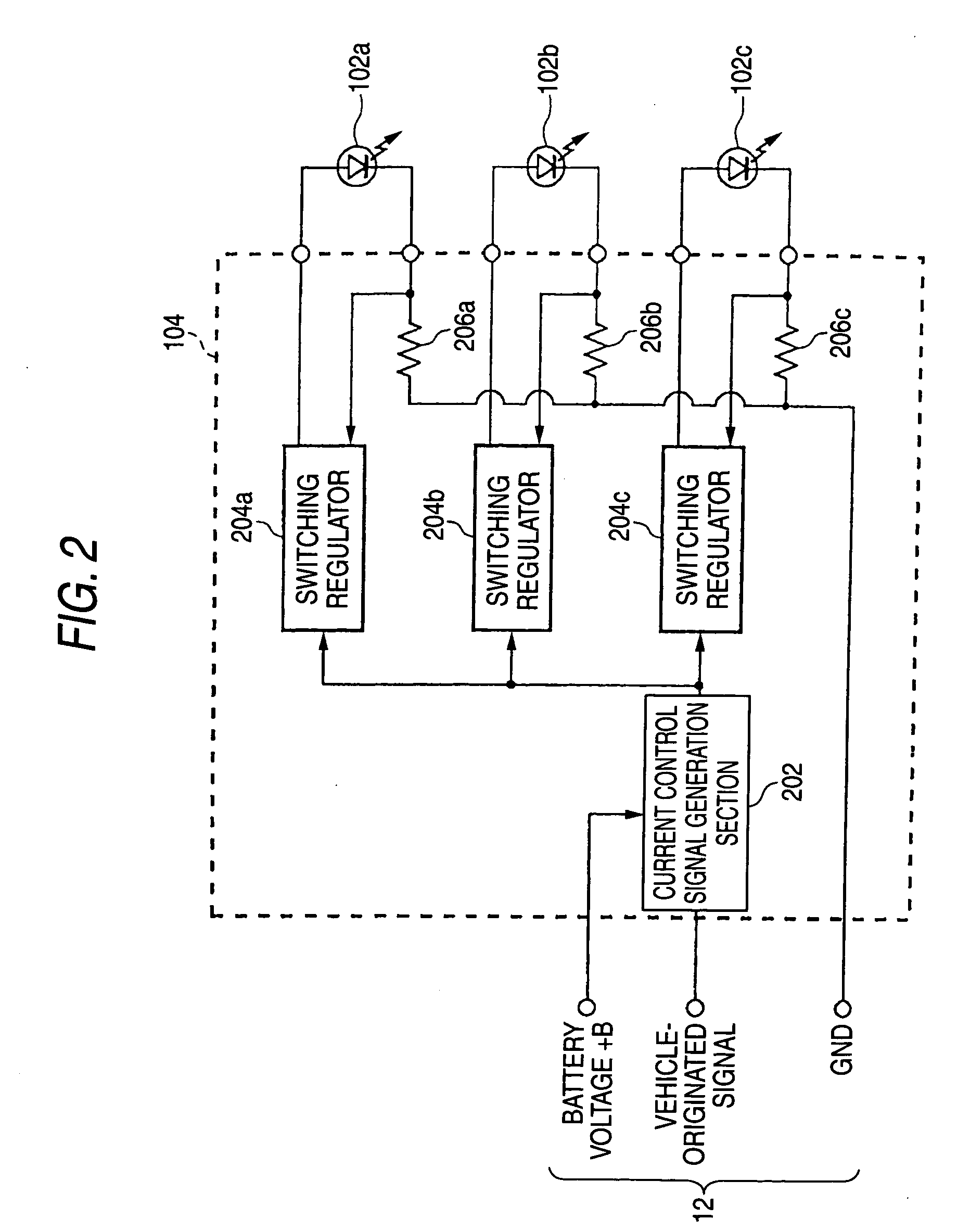
[0025] The plurality of light source modules 1...


PUM


Abstract

A vehicle head lamp is disclosed for use in a vehicle, and includes a plurality of semiconductor light sources which differ in directions of radiation; an optical system disposed for common use by the plurality of semiconductor light sources; and a luminous energy control section for changing a ratio among luminous energies emitted by the respective semiconductor light sources in accordance with a vehicle-originated signal provided by a vehicle-side. In addition, the luminous energy control section may change the ratio among the luminous energy in accordance with a rotation angle by means of receiving a signal indicating a rotation angle of a steering wheel as the vehicle-originated signal.

Description

[0001] This application claims foreign priority based on Japanese Patent application No. 2004-040790, filed Feb. 18, 2004, the contents of which is incorporated herein by reference in its entirety. BACKGROUND OF THE INVENTION [0002] 1. Field of the Invention [0003] The present invention relates to a vehicle lamp. [0004] 2. Description of the Related Art [0005] Conventionally, a vehicle lamp employing a light-emitting diode element is known (see, e.g., JP-A-2002-231013) . In addition, some vehicle lamps employ a plurality of light-emitting diode elements for the purpose of, for instance, attaining desired light distribution. [0006] In recent years, a technique for changing light distribution by means of changing an orientation of a light source or of an optical system has been adopted in, for instance, a vehicle headlamp. However, when the technique is applied to a vehicle lamp which employs a plurality of light-emitting diode elements, in some cases, a number of driving members are ...

Claims


Application Information

Patent Timeline
IPC IPC(8): B60Q1/16B60Q1/12B60Q1/14B60Q1/24F21S8/10
CPCB60Q1/12B60Q1/143B60Q1/24F21Y2101/02B60Q2300/122F21S48/115B60Q2300/054F21Y2115/10F21S41/141F21S41/143F21S41/147F21S41/148
Inventor TAKEDA, HITOSHIITO, MASAYASU
Owner KOITO MFG CO LTD
Why Eureka
Try Eureka