
Vehicle-mounted laser radar optical system based on Light Tools and working method for same

A technology of vehicle-mounted laser radar and optical system, which is applied in the field of vehicle-mounted laser radar to achieve the effects of reducing optical components, reducing development costs, and reducing volume

Active Publication Date: 2016-04-06
DALIAN ROILAND SCI & TECH CO LTD
View PDF7 Cites 8 Cited by
  • Summary
  • Abstract
  • Description
  • Claims
  • Application Information

AI Technical Summary

Problems solved by technology

In the prior art, the photodetector can only finally receive a small part of the laser output laser energy; during the swinging process of the swing mirror, a lot of light cannot be reflected by the half-transparent mirror and enter the focusing lens, so it is received by the photodetector

Method used


Image

  • Vehicle-mounted laser radar optical system based on Light Tools and working method for same
  • Vehicle-mounted laser radar optical system based on Light Tools and working method for same
  • Vehicle-mounted laser radar optical system based on Light Tools and working method for same

Examples


Embodiment 1

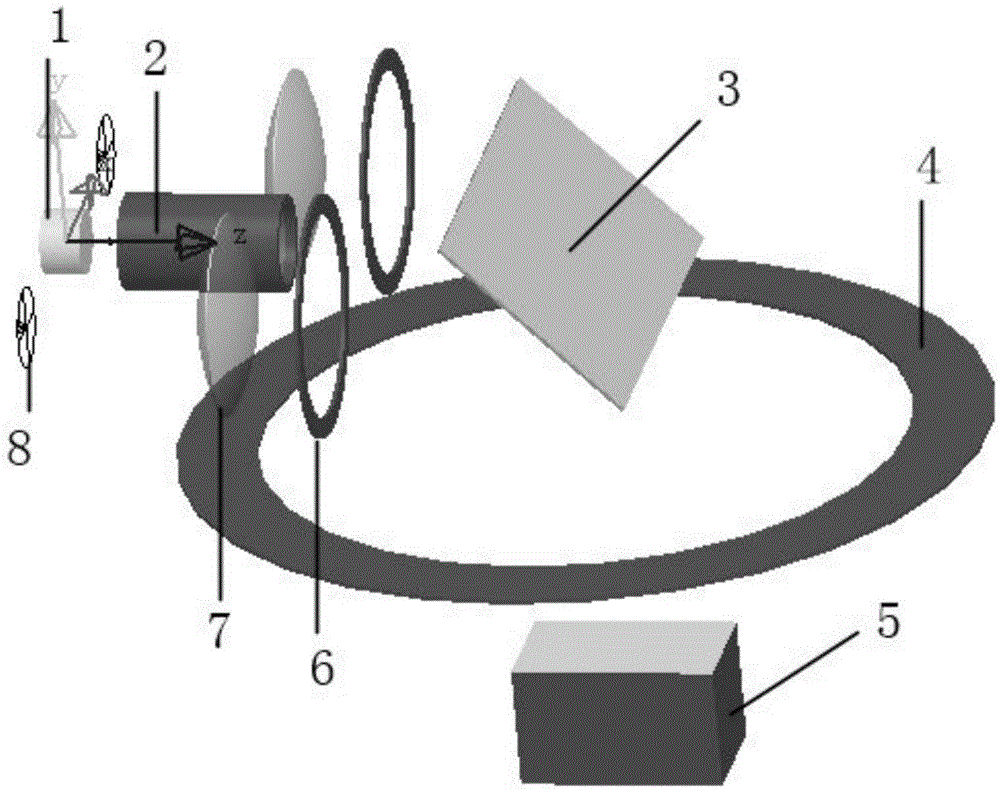
[0035] The optical system of automotive lidar based on LightTools includes:

[0036] Pulse laser 1, used to emit laser beam;

[0037] The collimating beam expander is placed in front of the pulse laser 1, and the laser beam passes through the beam expander 2, to achieve collimation and compression of the beam, reduce the laser divergence angle, and irradiate the surface of the pendulum mirror 3;

[0038] The pendulum mirror 3 is arranged obliquely relative to the beam expander 2, and the laser beam is reflected by the pendulum mirror 3 and irradiated to the target surface through the emission window 4; the surface of the pendulum mirror 3 illuminated by light is coated with an antireflection film.

[0039] The emission window 4, located under the swing mirror 3, allows laser beams of working wavelength to be transmitted and attenuates laser beams of other wavelengths;

[0040] The detection target 5 is placed under the emission window 4, the laser beam irradiates the target surface, and...


PUM


Abstract

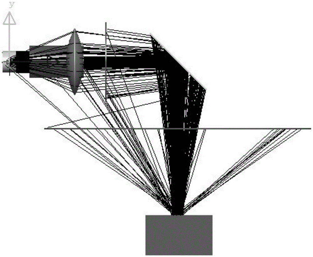
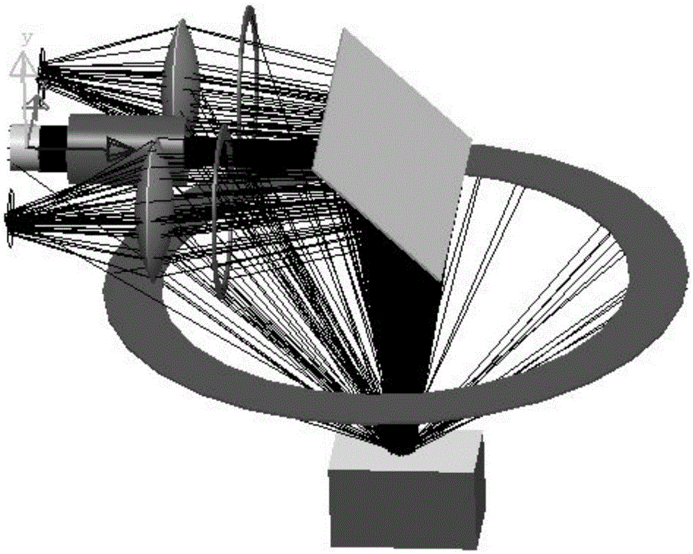
The invention provides a vehicle-mounted laser radar optical system based on Light Tools and a working method for the same. The system comprises a pulse laser, a beam expansion lens, a sway lens, variable lens diaphragms, focusing lenses and a photoelectric detector, wherein the pulse laser gives out laser beams; the beam expansion lens is placed in front of the pulse laser, the laser beams pass through the beam expansion lens to be collimated and compressed, decreased in laser divergence angle, and irradiated to the surface of the sway lens; the sway lens is disposed in an inclined manner relative to the beam expansion lens, and the laser beams are irradiated to the surface of a target by an emission window after being reflected by the sway lens; the variable lens diaphragms are disposed on two sides of the beam expansion lens, and parts of the laser beams are reflected by the sway lens and then enter the variable lens diaphragms; the focusing lenses are disposed on two sides of the beam expansion lens, and parts of the laser beams pass through the focusing lenses and are then focused and irradiated to the photoelectric detector; and the photoelectric detector is disposed behind the focusing lenses, and parts of the laser beams are irradiated to a photosurface center of the photoelectrical detector. The system and the working method provided by the invention increase optical energy which can be received by the photoelectric detector, increase a detection distance of a laser radar system, simplify an optical system of a traditional laser radar and reduce research and development cost.

Description

Technical field [0001] The invention belongs to the field of vehicle-mounted laser radar, in particular to a vehicle-mounted laser radar optical system based on LightTools and a working method thereof. Background technique [0002] The application of Lidar in automotive collision avoidance adaptive cruise control (ACC) systems, advanced driver assistance systems (ADAS) and unmanned driving systems have emerged in recent years. Vehicle-mounted lidar system required for intelligent driving of automobiles: It does not require massive data like surveying and mapping lidar to obtain high-precision environmental information, and is not satisfied with the low point cloud density of industrial security systems. It is necessary to design a specific and efficient dedicated system according to the vehicle road application environment, and realize real-time target recognition under the premise that it can effectively detect the point cloud density of road obstacles. [0003] Vehicle-mounted l...

Claims


Application Information

Patent Timeline
Patent Type & Authority Applications(China)
IPC IPC(8): G01S17/93G01S7/481
CPCG01S7/4812G01S17/931
Inventor 田雨农吴文周秀田史文虎
Owner DALIAN ROILAND SCI & TECH CO LTD
Learn More