Image plane interference microimaging device and method

A microscopic imaging and hyperspectral technology, applied in interference spectroscopy, spectrum investigation, etc., can solve problems such as energy reduction, signal-to-noise ratio and spectral resolution limitation, and achieve increased range, improved spectral resolution, and optical energy. big effect

Inactive Publication Date: 2013-04-24
NANJING UNIV OF SCI & TECH
View PDF4 Cites 9 Cited by
  • Summary
  • Abstract
  • Description
  • Claims
  • Application Information

AI Technical Summary

Problems solved by technology

But the main disadvantage is that the signal-to-noise ratio and spectral resolution of the system are limited by the width of the slit. The narrower the slit, the higher the spectral resolution, but the energy received by the system is also reduced.

Method used


Image

  • Image plane interference microimaging device and method
  • Image plane interference microimaging device and method

Examples


Embodiment Construction

[0023] The specific implementation manners of the present invention will be further described in detail below in conjunction with the accompanying drawings and examples. The following examples are used to illustrate the present invention, but are not intended to limit the scope of the present invention.

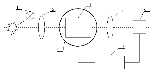
[0024] combine figure 1 , including a light source 1, a microscope objective lens 2, a transverse shearing beam splitter 3, an electronically controlled rotating table 4, an imaging objective lens 5, an area array CCD camera 6 and a computer 7. A light source 1, a microscope objective lens 2, a transverse shearing beam splitter 3, an imaging objective lens 5, and an area array CCD camera 6 are arranged in sequence along the optical path. The transverse shearing beam splitter 3 is fixed on the electronically controlled rotary table 4, and the computer 7 is respectively connected with the electronically controlled rotary table 4 and the area array CCD camera 6, and the compute...


PUM


Abstract

The invention relates to an image plane interference microimaging device and a method. The device comprises a light source, a microscope objective, a transverse shear beam splitter, an electric control rotary platform, an imaging objective, an area array charge coupled device (CCD) camera and a computer. The method includes that objects at a lighting site are imaged by an infinity conjugate microscope objective and then are emitted into the transverse shear beam splitter as parallel light, each light beam is transversely shore by the transverse shear beam splitter, and two light beams parallel to each other are obtained. After the light passes through the imaging objective, interference fringes are produced by the area array CCD camera; the electric control rotary platform is controlled and driven by the computer to achieve pushing imaging for the objects; and light intensity corresponding to the observing objects in each image is drawn from image sequences, interference information of the observing objects is combined again, and Fourier exchange calculation inversion is conducted for the interference information to obtain light spectrum information of the observing information. The image plane interference microimaging device is large in luminous flux, high in signal to noise ratio, and high in resolution ratio.

Description

technical field [0001] The discovery relates to the field of microscopic hyperspectral imaging, specifically a hyperspectral microscopic imaging device and method combining microscopic imaging technology and interference imaging spectroscopy technology. Background technique [0002] Spectral analysis is an important research method in natural science. Spectral technology can detect information such as the physical structure and chemical composition of the measured object. Spectral imaging technology is the product of the perfect combination of spectral analysis technology and image analysis technology. It not only has spectral resolution ability, but also image resolution ability, and can perform qualitative, quantitative and positioning analysis on targets. Interferometric imaging spectroscopy technology is a cutting-edge spectral detection technology in the field of spectral imaging. It uses the Fourier transform relationship between the interferogram and the light source ...

Claims


Application Information

Patent Timeline
Patent Type & Authority Applications(China)
IPC IPC(8): G01J3/45
Inventor 李建欣周伟孟鑫史今赛郭仁慧沈华马骏朱日宏陈磊何勇
Owner NANJING UNIV OF SCI & TECH
Why Eureka
Try Eureka