Motorized watercraft

a motorized watercraft and watercraft technology, applied in the field of motorized watercraft, can solve the problems of complex design of the structure unusable maintenance, and difficult handling of the motorized watercraft, and achieve the effect of simple maintenance or repair

Inactive Publication Date: 2005-08-18
GRIMMEISEN ANDREA
View PDF25 Cites 13 Cited by
  • Summary
  • Abstract
  • Description
  • Claims
  • Application Information

AI Technical Summary

Benefits of technology

[0032] One embodiment is advantageous for the two different types of employment of the motorized watercraft while in the prone or standing position, which is distinguished because a remote control device is assigned to the underwater drive unit, which is releasably attached to the hull of the craft and can be brought into operative contact with the control device of the underwater unit over a wireless transmission path.
[0033] For a simple maintenance or repair of the underwater drive unit, the hull of the craft has a plate, flap or the like which can be opened, in the flow channel below the underwater drive unit, through which access to the underwater unit is provided.

Problems solved by technology

The design of the structure of the motorized watercraft is complicated and is not user-friendly with respect to maintenance.
The output of such a motorized watercraft is relatively limited.
Also, because of its complex structure the motorized watercraft is very heavy and therefore difficult to handle.

Method used


Image

  • Motorized watercraft
  • Motorized watercraft
  • Motorized watercraft

Examples


Embodiment Construction

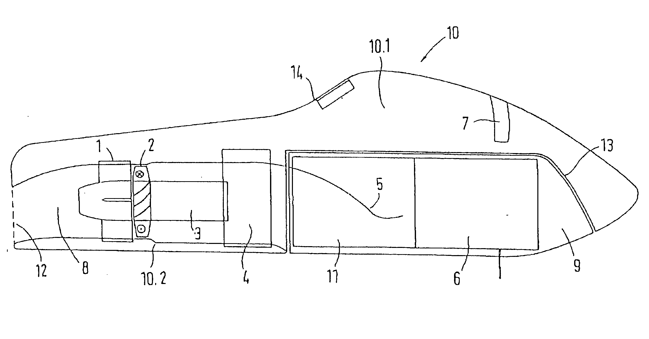
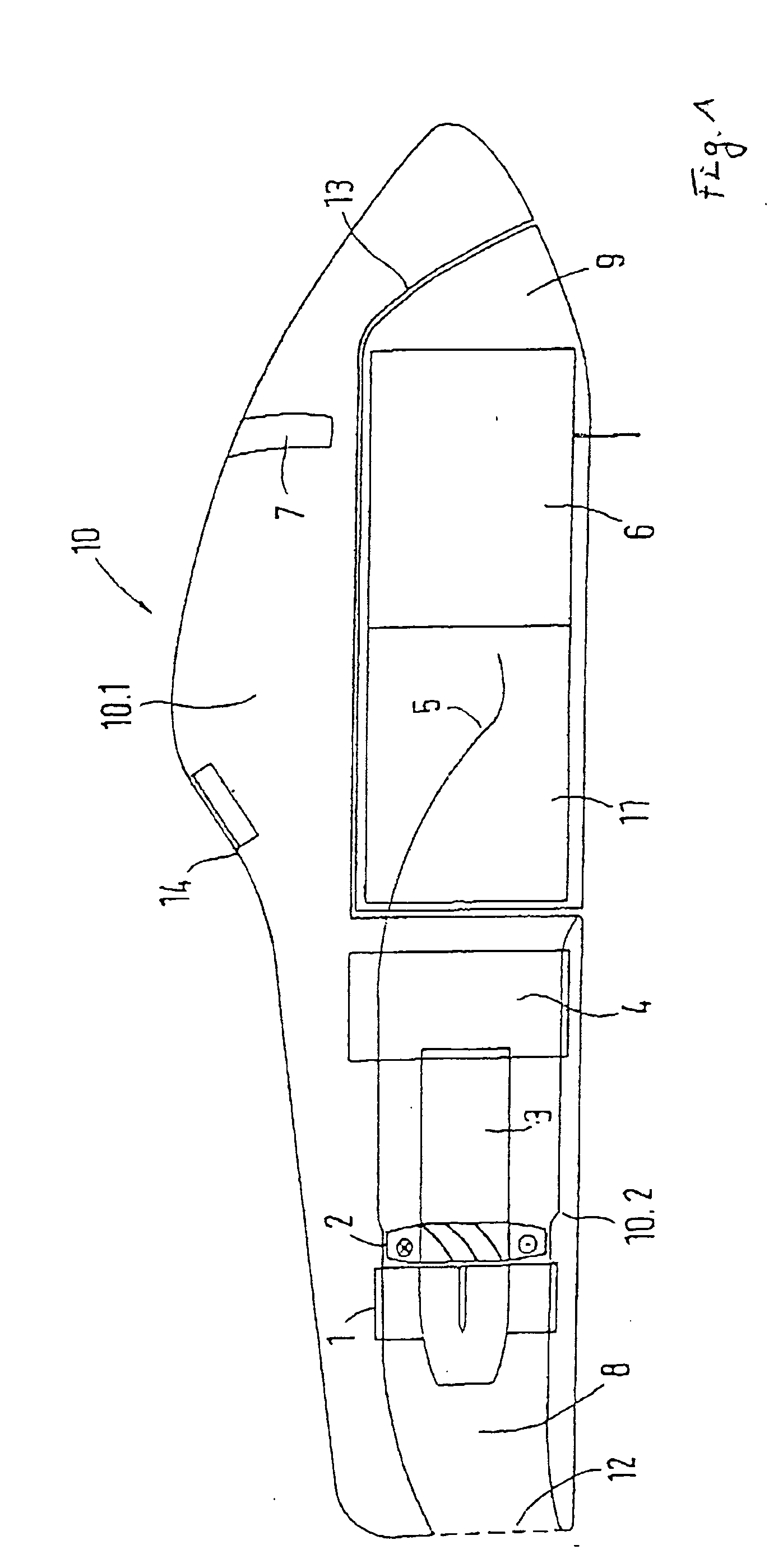
[0037] The exterior shape of the hull 10 of the craft essentially corresponds to the exterior shape of the hull of the motorized watercraft known from PCT International Publication WO 96 / 30087. The flow channel 8 extends from the inflow opening 11 in the area of the bow to the flow outlet 12 in the area of the stern of the hull 10 of the craft. Therefore the inflow opening 11 extends, starting from a center area of the hull 10 of the craft, in the direction toward the bow. An underwater drive unit comprising a flow stator 1, an electric motor 3, a water screw 2 and the motor control device 4 is installed in the flow channel 8, which is slightly downward curved in the area of or near the inflow opening 11 and the outflow opening 12. In this case, the flow stator is in stationary connection with the hull 10 of the craft and it has a function that straightens the rotating water flow generated in the flow channel 8 so that it is as free as possible of torsion or torsional forces. An inc...


PUM


Abstract

A motorized watercraft with a hull of the craft on which a user lies prone, at least partially, or stands up, with a flow channel extending in the hull of the craft with an electric motor-driven water screw. The electric motor and the batteries, as well as the control device for the electric motor and the water screw are housed, at least partially, in the flow channel in the hull of the craft. A clear increase in efficiency can be attained in connection with the motorized watercraft if a flow stator is arranged in the flow channel of the water screw, upstream, or preferably downstream, in the flow direction, which at least partially straightens the rotating water flow generated in the flow channel.

Description

BACKGROUND OF THE INVENTION [0001] 1. Field of the Invention [0002] This invention relates to a motorized watercraft with a hull of the craft, on which the user lies prone, at least partially, or stands up, with a flow channel extending in the hull of the craft with an electric motor-driven water screw, wherein the electric motor and the batteries, as well as the control device for the electric motor and the water screw are housed, at least partially, in the flow channel in the hull of the craft. [0003] 2. Discussion of Related Art [0004] A motorized watercraft of this type is known from PCT International Publication WO 96 / 30087. There, the user lies prone on the hull of the craft, and the water screw in the flow channel is driven by a battery-powered electric motor so that a water flow, which extends opposite the movement direction of the motorized watercraft, is aspirated through the flow channel. [0005] Thus the water flow can be kept away from the user, and the flow of the chann...

Claims


Application Information

Patent Timeline
Patent Type & Authority Applications(United States)
IPC IPC(8): B63B35/73
CPCB63B35/731B63B34/10B63H21/17B63H2011/081
Inventor GRIMMEISEN, ANDREA
Owner GRIMMEISEN ANDREA
Why Eureka
Try Eureka