Method and apparatus for determining at least an indication of return loss of an antenna

a technology of antenna return loss and measurement method, which is applied in the direction of transmission monitoring, diversity/multi-antenna system, transmission monitoring, etc., to achieve the effect of preventing revenue loss

Inactive Publication Date: 2005-08-18
LUCENT TECH INC
View PDF4 Cites 41 Cited by
  • Summary
  • Abstract
  • Description
  • Claims
  • Application Information

AI Technical Summary

Benefits of technology

[0009] The present invention provides a more accurate method and apparatus for determining at least an indication of antenna retu

Problems solved by technology

However, for short cables, these measurements may not

Method used


Image

  • Method and apparatus for determining at least an indication of return loss of an antenna
  • Method and apparatus for determining at least an indication of return loss of an antenna
  • Method and apparatus for determining at least an indication of return loss of an antenna

Examples


Embodiment Construction

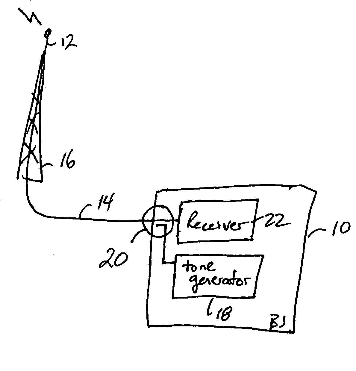
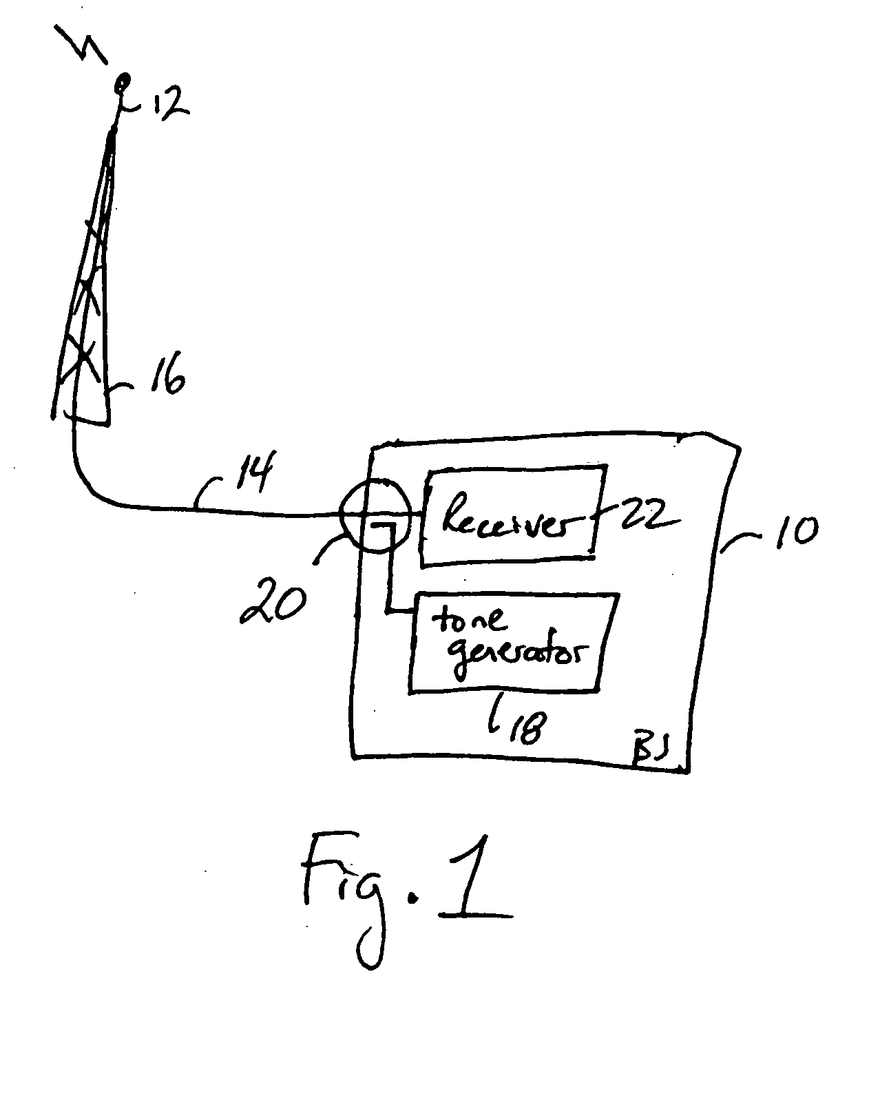
[0015]FIG. 1 illustrates an example of communication equipment that may employ one or more of the embodiments of the present invention. Specifically, FIG. 1 illustrates the example of a base station connected to an antenna. As shown, a base station 10 is connected to an antenna 12 by a cable 14. The base station 10 is disposed at the bottom of an antenna mast 16 supporting the antenna 12. However, it will be understood that the base station 10 may be tower mounted, and thus disposed closer to the antenna 12.

[0016] The base station 10 includes a tone generator 18. The tone generator 18 generates, for example, a carrier wave or continuous wave (CW) tone. This test signal is coupled in the forward direction of the cable 14 towards the antenna 12 by a directional coupler 20. A receiver 22 of the base station 10 includes, among other things, an RF power detector (e.g., a received signal strength (RSSI) detector) for detecting the amount of power of the test signal reflected back to the ...


PUM


Abstract

A tone generator generates a test signal that a coupler injects into a cable towards an antenna. A receiver or other communication equipment, connected to the antenna via the cable, measures, across a frequency band, at least powers of a signal received at a base station from the antenna. The received signal includes a leakage signal and a reflected signal where the reflected signal is a reflected portion of the test signal and the leakage signal is a portion of the test signal leaking from the coupler away from the antenna. The communication equipment determines maximum and minimum powers of the received signal based on the measurements, and determines at least an indication of return loss of the antenna based on the determined maximum and minimum powers.

Description

BACKGROUND OF THE INVENTION [0001] 1. Field of the Invention [0002] The present invention relates to measuring return loss of an antenna such as in a wireless communication system. [0003] 2. Description of Related Art [0004] In communication equipment such as mobile communication base station equipment it is desirable to have a means of determining if an antenna is connected satisfactorily to the equipment. Typically the communication equipment is connected to an antenna by a cable. Incorrect installation, storm damage or aging effects can all lead to an inadequate connection. [0005] An antenna return loss, or ‘VSWR’ (Voltage Standing Wave Ratio) measurement is a common method of determining the quality of the antenna connection. In such a measurement, a radio frequency (RF) tone is coupled into the cable in the direction of the antenna. An RF power detector, within, for example, a receiver of the communication equipment connected to the antenna, determines how much of this tone is ...

Claims


Application Information

Patent Timeline
IPC IPC(8): H04B7/10H04B17/00
CPCH04B17/309H04B17/354H04B17/327H04B17/103
Inventor KANG, JOSEPH H.WEDGE, DAVID J.
Owner LUCENT TECH INC
Why Eureka
Try Eureka