Traveling wave based fault location using unsynchronized measurements for transmission lines

Active Publication Date: 2021-12-21
HITACHI ENERGY LTD
View PDF2 Cites 0 Cited by
  • Summary
  • Abstract
  • Description
  • Claims
  • Application Information

AI Technical Summary

Benefits of technology

[0002]The present invention generally relates to fault location in power transmission lines. More specifically, the present invention relates to travelling wave based fault location with measurements at two ends of a power transmission line.
[0003]Faults in transmission lines can occur because of bad weather conditions (e.g. due to storms, lightning, snow, freezing, rain), electrical disturbances (e.g. insulation breakdown, short circuits etc.) etc. Quick identification of fault location improves the reliability, availability and may prevent revenue losses.

Problems solved by technology

There may be an electrical fault (or disturbance) at a particular location in the power transmission line.

Method used


Image

  • Traveling wave based fault location using unsynchronized measurements for transmission lines
  • Traveling wave based fault location using unsynchronized measurements for transmission lines
  • Traveling wave based fault location using unsynchronized measurements for transmission lines

Examples


Embodiment Construction

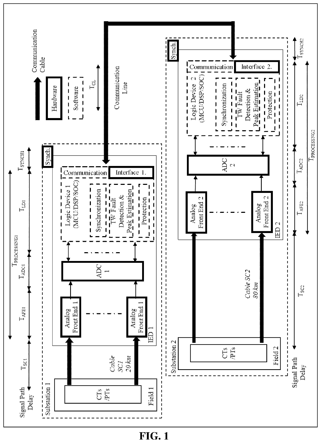
[0037]Consider the hardware and software representation of an IED system shown in FIG. 1. IED 1 and IED 2 are placed in respective substations 1 and 2, and receive voltage and / or current signals from field 1 and 2 respectively via copper substation cables (SC1 and SC2). Both substations are connected to each other via communication line (CL) for data exchange. Assuming fault location calculation is being performed at IED 1, a signal delay can be calculated using:

Signal delay of field 1 data at IED1=TSC1+TPROCESSING1+TSYNCH1   (A.1)

Signal delay of field 2 data at IED2=TSC2+TPROCESSING2+TSYNCH2+TCL  (A.2)

[0038]Typically, a synchronization means like GPS can give synchronization accuracy of micro-seconds or less. However, there are a number of practical difficulties in achieving the estimated data synchronization level between two IEDs as explained below.

[0039]Non-Identical Synchronization Device Errors (ΔTSYNCH=TSYNCH1−TSYNCH2):

[0040]All time synchronization systems including GPS, int...


PUM


Abstract

A method can be used to determine a fault location in a power transmission line that connects a first terminal with a second terminal. Parameters associated with travelling waves are detected from measurements carried out at the first and second terminals. The parameters include arrival times of first and second peaks of the travelling waves at the first and second terminals respectively, and rise times of the first peaks of corresponding travelling waves. A first half, a second half, or a mid-point of the power transmission line is identified as having a fault based on the parameters. The fault location can be estimated based on the arrival times of the first and second peaks of the travelling waves detected from measurements carried out at the first and second terminals, a velocity of propagation of the travelling wave in the power transmission line, and / or a length of the power transmission line.

Description

CROSS-REFERENCE TO RELATED APPLICATIONS[0001]This patent application is a national stage filing of International Application No. PCT / IB2018 / 054380, filed on Jun. 14, 2018, which claims the benefit of Indian Patent Application No. 201741041164, filed Nov. 17, 2017, which applications are hereby incorporated by reference in their entirety.FIELD OF THE INVENTION[0002]The present invention generally relates to fault location in power transmission lines. More specifically, the present invention relates to travelling wave based fault location with measurements at two ends of a power transmission line.BACKGROUND OF THE INVENTION[0003]Faults in transmission lines can occur because of bad weather conditions (e.g. due to storms, lightning, snow, freezing, rain), electrical disturbances (e.g. insulation breakdown, short circuits etc.) etc. Quick identification of fault location improves the reliability, availability and may prevent revenue losses.[0004]Fault location methods are classified int...

Claims


Application Information

Patent Timeline
Patent Type & Authority Patents(United States)
IPC IPC(8): G01R31/08H02J3/18
CPCG01R31/085G01R31/088H02J3/1807H02H7/265
Inventor NAIDU, OBBALAREDDI DEMUDUGORE, RAHUL NANDKUMARKUBAL, NANDKISHOR
Owner HITACHI ENERGY LTD
Why Eureka
Try Eureka