Radio communication system

a radio communication system and radio communication technology, applied in the field of digital radio communication systems, can solve the problems of limited service area, limited volume of lines that can be accommodated in a single cell, limited radio transmission range, etc., and achieve the effect of accurate handoff procedur

Active Publication Date: 2005-08-18
SNAPTRACK
View PDF6 Cites 114 Cited by
  • Summary
  • Abstract
  • Description
  • Claims
  • Application Information

AI Technical Summary

Benefits of technology

[0044] If (the number of subcarriers with Conditions 2+3>the number of subcarriers with Condition 1), then the han

Problems solved by technology

Further, the range of radio transmission is limited and all of the service areas cannot be covered by a single base station (“access point”; to be hereafter referred to as “access point AP”).
However, since in this type of system the frequencies that can be actually used in a single cell are only a fraction of the frequencies that are allocated to the entire system, the volume of lines that can be accommodated in a single cell is limited.
The use of the second time slot TS2 for communications between the second access point AP2 and the terminal would result in a large radio interference due to the communications going on between the first access point AP1 and the terminal.
In the conventional frequency division method, it is difficult to freely change the frequency width due to the limitations of analog circuits, such as filters.
If these conditions are not met, problems arise

Method used


Image

  • Radio communication system
  • Radio communication system
  • Radio communication system

Examples


first embodiment

[0067] A radio communication system according to the invention will be described by referring to the drawings.

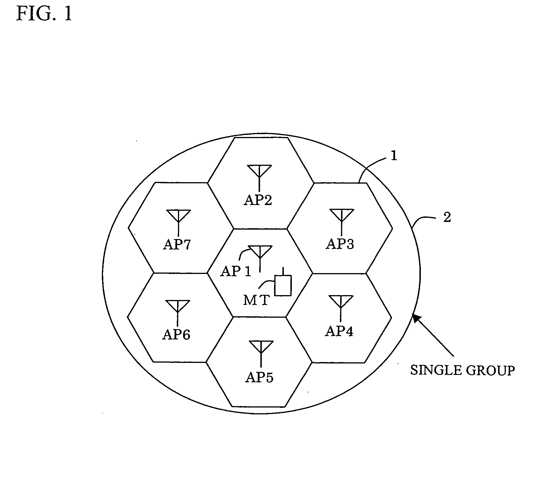
[0068] A case will be described in which terminals exist in a cell in which an access point is present. The terminals are connected as communication systems to the network by conducting communications with the access point. For this purpose, a time slot must be determined in which the communications with the access point are conducted.

[0069] In accordance with the invention, a time slot among all of the time slots provided for the access point by the system that is not allocated to any other terminals in the station can be freely allocated for communications with a particular terminal.

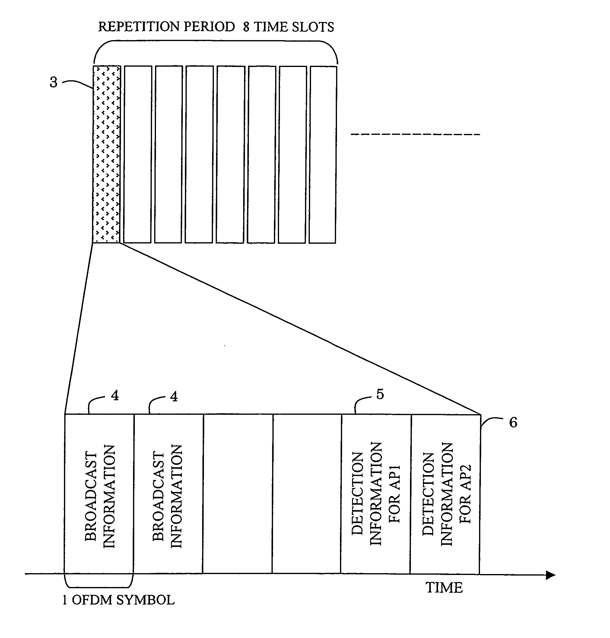
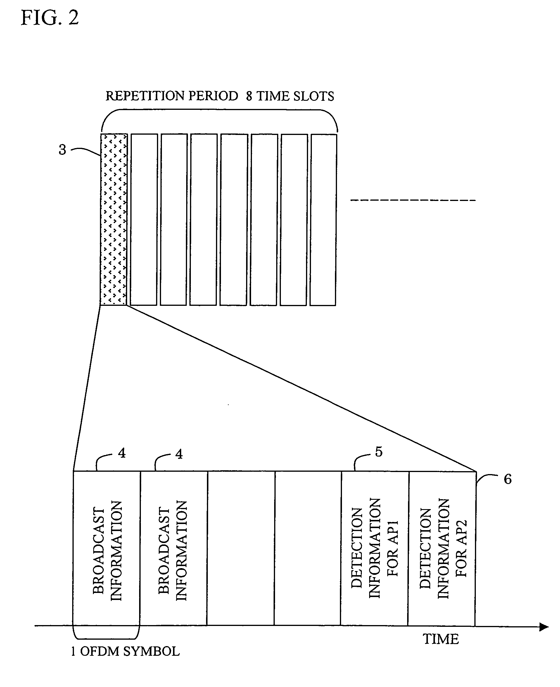
[0070] The access point periodically transmits, for example, a detection signal that is used by the terminals in measuring the intensity of a signal from the access point and comparing it with the intensity of an interference signal.

[0071] The detection signal must be transmitted by all of t...

second embodiment

[0101] Hereafter, the radio communication system according to the invention will be described by referring to the drawings.

[0102] The radio communication system of the second embodiment is characterized by a technique relating to the handoff process for the movement of a terminal across cells.

[0103] The handoff process is a procedure allowing for a seamless transfer of access points such that the terminal as it moves can be connected to the radio communication system continuously.

[0104] Referring to FIG. 7, in one example of the handoff process, the intensity of radio waves from the two access points AP (AP1 and AP2) are compared in the terminal MT, and then a request is made for a handoff process. In another, an optimum access point AP is selected between the access points AP based on the intensity of the radio wave from the terminal MT, delay time, and so on, and then instructions are made on the part of the radio communication system based on the selection. Generally, a handoff...


PUM


Abstract

A TDMA radio communication system using a multiple subcarrier modulation method and comprising at least a first and a second radio station. The first radio station carries out communications by selectively modulating a subcarrier with which a desired transmission rate can be obtained in the second radio station, thereby providing a radio communication system that does not require the monitoring of each time slot by a terminal.

Description

FIELD OF THE INVENTION [0001] The present invention relates to digital radio communication systems and more particularly to a method of enabling a fast and stable communication to be carried out in a cellular system with planar or horizontal service areas in which cells are constructed using the same frequency. BACKGROUND ART [0002] In radio systems, such as one for cellular phones, for example, radio services must cover communication areas in a planar fashion. Further, the range of radio transmission is limited and all of the service areas cannot be covered by a single base station (“access point”; to be hereafter referred to as “access point AP”). Accordingly, a plurality of access points AP are provided so that communications can continue despite the movement of terminal stations. [0003] Specifically, a system called “cell configuration” is employed, as shown in FIG. 9. Referring to FIG. 9, each hexagon represents a cell 32 at the center of which an access point AP 31 is located....

Claims


Application Information

Patent Timeline
IPC IPC(8): H04J3/00H04B7/26H04B17/40H04W28/18H04W72/08
CPCH04L5/0007H04L5/006H04L5/0046H04B7/2643H04W36/18
Inventor OKAMOTO, NAOKIMORINAGA, NORIHIKOSANPEI, SEIICHI
Owner SNAPTRACK
Why Eureka
Try Eureka