
Catheter with stiffening element

Inactive Publication Date: 2005-08-18
WILLIAM COOK EURO
View PDF12 Cites 86 Cited by
  • Summary
  • Abstract
  • Description
  • Claims
  • Application Information

AI Technical Summary

Benefits of technology

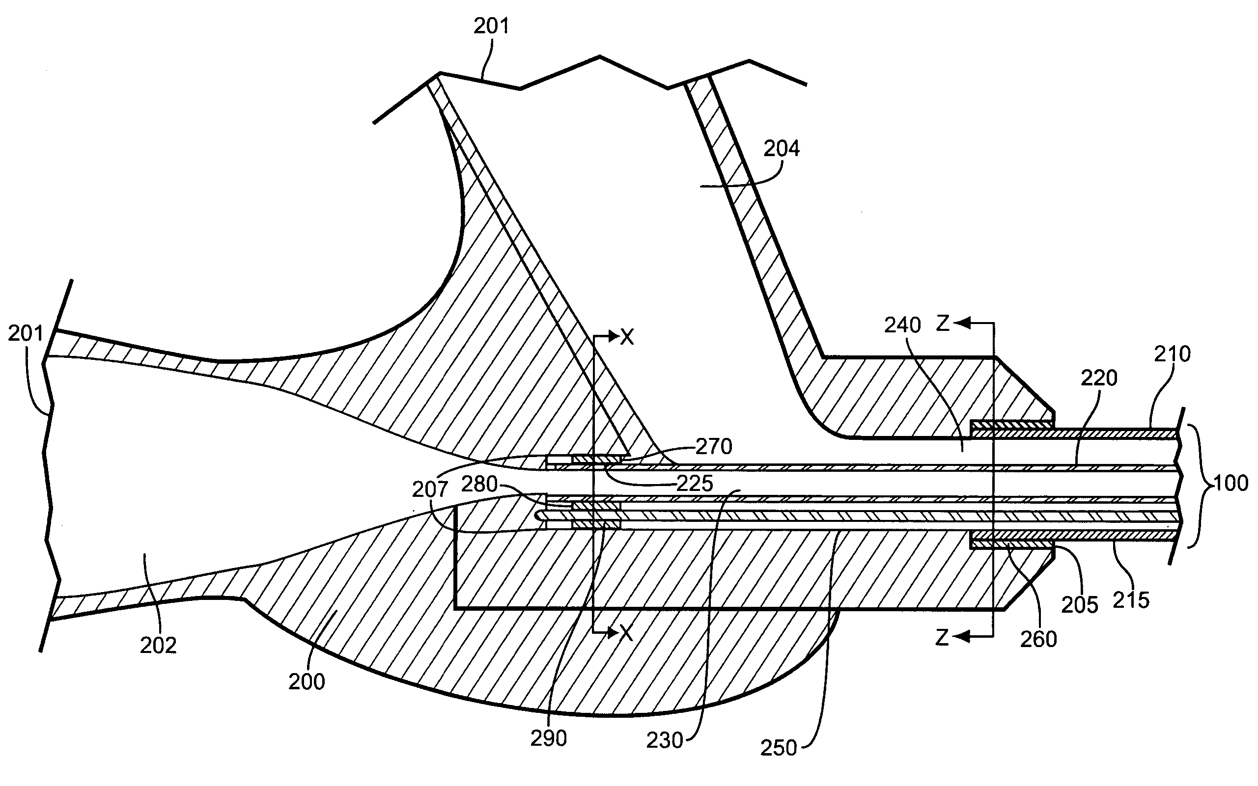
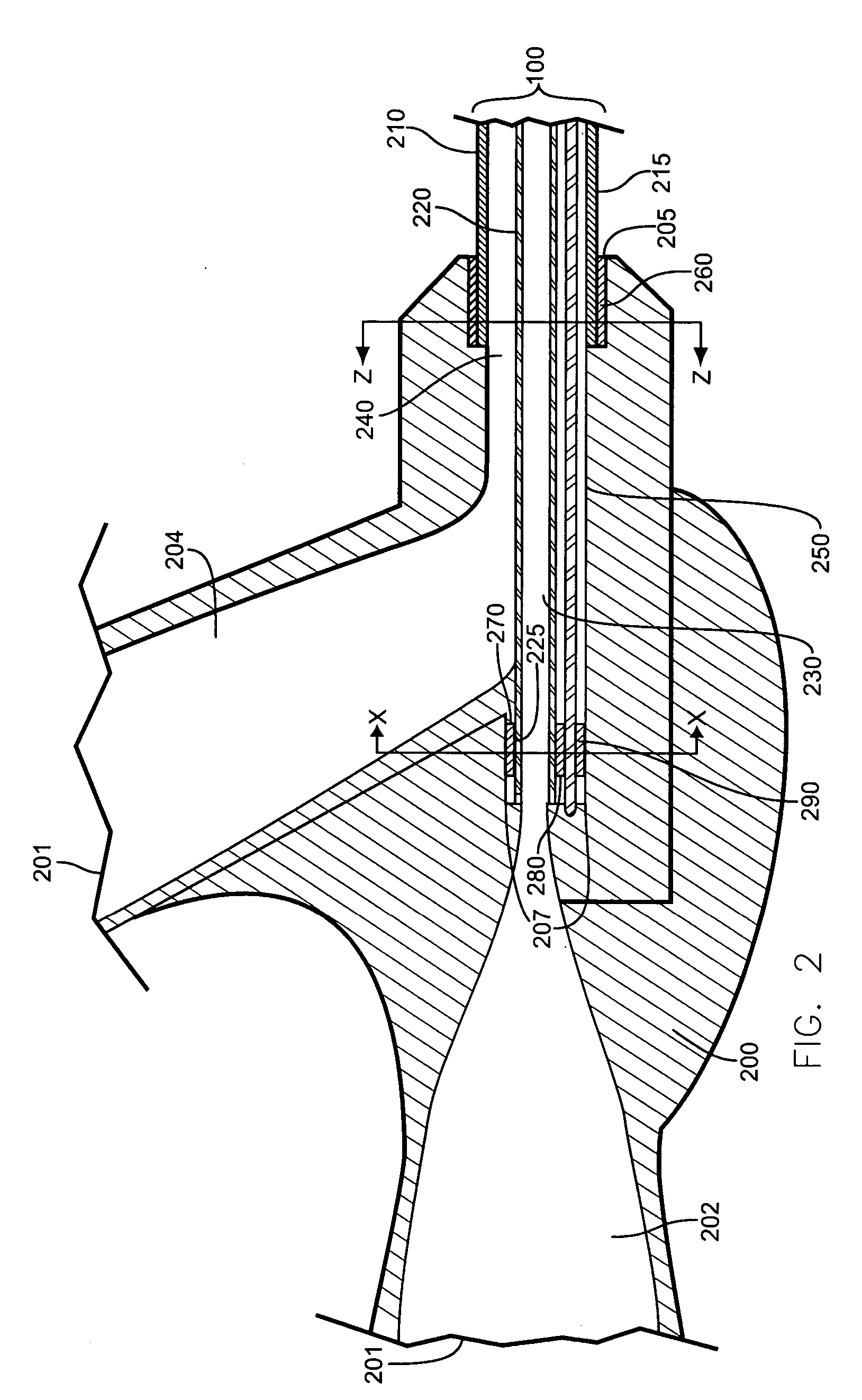
[0010] A catheter is provided that includes a stiffening element placed in a lumen of the catheter. The catheter may include an elongate body having a plurality of lumens, such as a first lumen and a second lumen. The first lumen may be defined by an inner tube, while the second lumen may be defined by the space between the inner surface of an outer tube and the outer surface of the inner tube. A hub may be coupled to the proximal end of the catheter body having first and second access hubs in fluid communication with the first and second lumens, respectively. The stiffening element may run longitudinally in one of the lumens and be coupled to the hub and a proximal end of the inner tube. The stiffening element can enhance the resistance of the catheter body to compression along its longitudinal axis.

Problems solved by technology

The process of guiding a catheter through a vessel becomes very difficult when the vessel becomes small and when the target site is deep within the vascular.
When a catheter is tracked over a wire guide, the progress or “pushab ility” of the catheter may be impeded by kinking and columnar collapse of the catheter onto the wire guide.
This problem is especially acute when the material from which the catheter is made is highly flexible to allow the catheter to pass over the difficult curves of the wire guide when the wire guide is positioned in a tortuous path.

Method used


Image

  • Catheter with stiffening element
  • Catheter with stiffening element
  • Catheter with stiffening element

Examples


Embodiment Construction

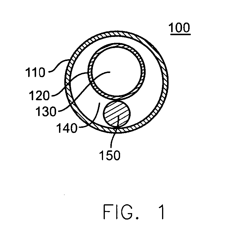
[0017]FIG. 1 depicts an axial cross-sectional view of an elongate, flexible catheter body 100 having a longitudinal axis extending between a proximal end and a distal end. The catheter body 100 may include a plurality of lumens, such as an inner lumen 130 and an outer lumen 140, defined by a plurality of tubes, such as outer tube 110 and inner tube 120, for example, and a stiffening element 150. The catheter body 100 may have a length in the range from about 40 centimeters (cm.) to about 200 cm., usually having a length in the range from about 60 cm. to about 175 cm. The diameter of the catheter body 100 may be in the range of about 0.67 millimeters (mm.) (2 F) to about 7 mm. (21 F).

[0018] The outer tube 110 may terminate proximal of the inner tube 120, thus being shorter in length. The outer tube 110 may have an external diameter of about 0.67 mm. to about 7 mm., while the inner tube 120 may have an external diameter of about 0.33 mm. to about 6 mm. The outer tube 110 also may hav...


PUM


Abstract

Catheters having a stiffening element are disclosed. The resultant catheters may include one or more access hubs. During use of the catheters, a stiffening element can provide an increased and variable resistance to deformation of the catheter body. The proximal end of the stiffening element may be coupled to the catheter hub. The stiffening element may move in the lumen it occupies as the catheter is threaded along the wire guide, thus allowing the catheter components to attain their lowest energy configuration at each bend.

Description

[0001] This application claims priority to U.S. Provisional Application No. 60 / 545,237, filed Feb. 17, 2004, which is hereby incorporated by reference herein.BACKGROUND [0002] Catheters are tube-like medical instruments that may be inserted into a body cavity, organ, or blood vessel for diagnostic or therapeutic reasons. Catheters may be designed for insertion into the vasculature and are available for a wide variety of purposes, including diagnosis, interventional therapy, drug delivery, drainage, perfusion, and the like. They also may be useful for other procedures, such as gynecological procedures, cardiac procedures, general interventional radiology procedures, and the like. Catheters for each of these and other purposes can be introduced to numerous target sites within a patient's body by guiding the catheter through an incision made in the patient's skin and a blood vessel and then through the body to the target site. [0003] Catheters generally have an elongated, flexible cath...

Claims


Application Information

Patent Timeline
IPC IPC(8): A61M25/00
CPCA61M25/005A61M2025/0063A61M25/0097A61M25/0053
Inventor AGGERHOLM, STEEN
Owner WILLIAM COOK EURO
Learn More