System and method for associating a DLPDU received by an interface chip with a data measurement made by an external circuit

a technology of external circuits and interface chips, applied in the field of hand-held diagnostic devices, can solve the problems of increasing the cost of individual field devices, internal circuitry, and insufficient to properly function,

Active Publication Date: 2005-08-18
FISHER-ROSEMOUNT SYST INC
View PDF35 Cites 26 Cited by
  • Summary
  • Abstract
  • Description
  • Claims
  • Application Information

AI Technical Summary

Problems solved by technology

When problems arise in communicating with a particular field device or if data received from the field device is anomalous, it is sometimes necessary to diagnose the problem manually.
However, such additional circuitry increases the cost of the individual field device.
Additionally, when transmission errors arise, such internal circuitry may be insufficient to properly identify the problem, sending messages indicating the field device is okay when in fact there is a problem.
Moreover, such extra circuitry places a power drain on the Fieldbus power supply that most of the time is unnecessary, resulting in wasteful power dissipation.
Such a device is intended to verify and to troubleshoot network operation, but, by itself, it cannot communicate on the Fieldbus segment.
Since the precise requirements of each field device vary, it is not always possible to provide a direct interface from the Fieldbus Interface Chip to the measurement circuit of the field device.
With current diagnostic devices and methods, troubleshooting communication problems and configuration errors associated with the field devices on the protocol bus is difficult.
As a result, users at the system level cannot easily identify the source of problems and are typically only informed by the system that the overall process is not operating properly.
When such an alert arises, it is difficult to identify and fix the errant field device.

Method used


Image

  • System and method for associating a DLPDU received by an interface chip with a data measurement made by an external circuit
  • System and method for associating a DLPDU received by an interface chip with a data measurement made by an external circuit
  • System and method for associating a DLPDU received by an interface chip with a data measurement made by an external circuit

Examples


Embodiment Construction

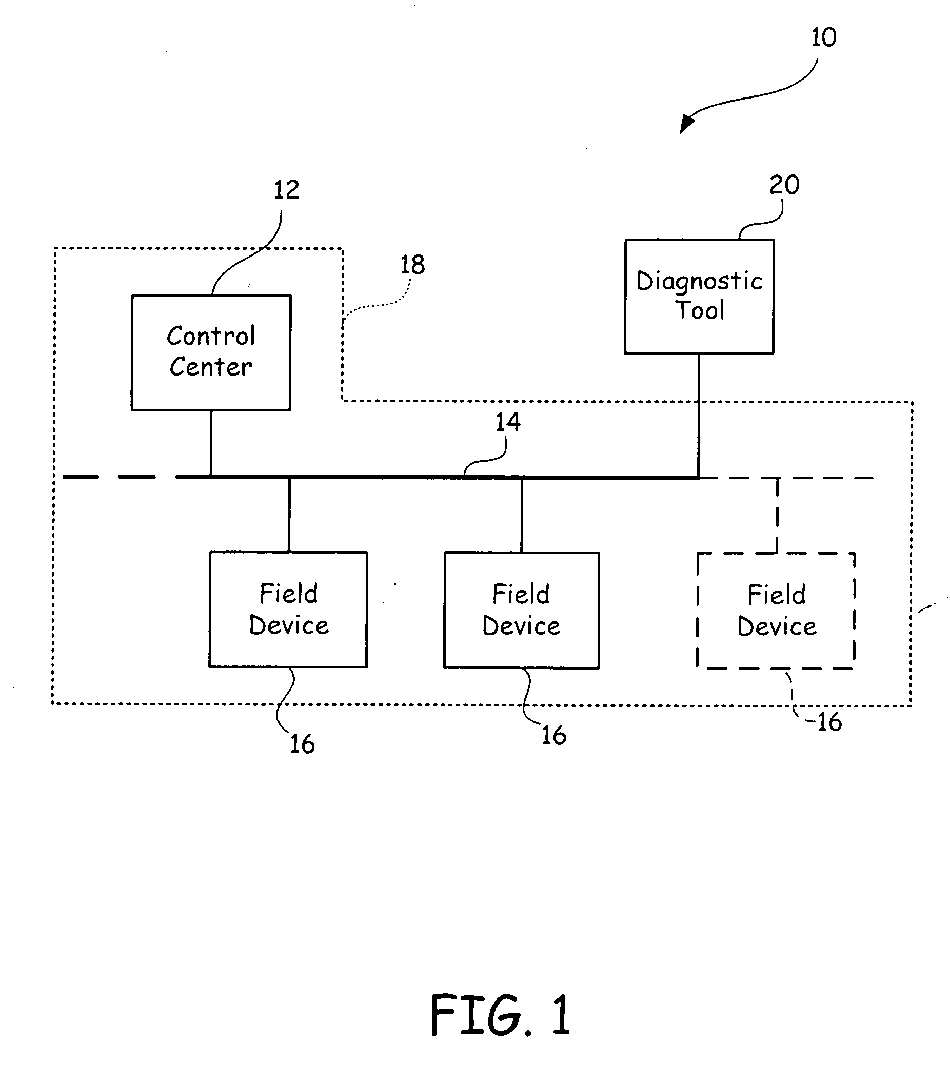
[0021]FIG. 1 shows a industrial control system 10 having a control center 12 connected via a homerun cable 14 to a plurality of field devices 16 to form a control network 18. A diagnostic tool 20 is connected to the network 18. The homerun cable 14 extends in phantom and an additional field device 16 is also shown in phantom to illustrate that the homerun cabling 14 may be extended and field devices 16 may be added to extend the control network 18 as needed.

[0022] Generally, the homerun cable 14 may be a two-wire, a three-wire or a four-wire twisted pair cabling such as with a traditional Fieldbus network. In typical plants, the homerun cable 14 may extend thousands of meters and numerous field devices 16 may be connected (via connectors, direct wiring or a junction box) to the control center 12 via the cabling 14, making the network 18 quite large.

[0023] As shown, a diagnostic tool 20 is connected to the homerun cabling 14 in order to identify problems with the control network 18...


PUM

PropertyMeasurementUnit
poweraaaaaaaaaa
sound energyaaaaaaaaaa
DC poweraaaaaaaaaa

Abstract

A diagnostic tool has a packet based network medium attachment unit, a measurement interface, a network interface, and a microprocessor for reading DLPDUs from a network segment and for taking simultaneous measurements of DLPDUs on the segment. The measurement data is associated with a stored DLPDU if the DLPDU is still active on the network segment when the measurement data is read by the microprocessor. The diagnostic tool utilizes a currently active attribute to determine the status of a DLPDU.

Description

BACKGROUND OF THE INVENTION [0001] The present invention generally relates to a diagnostic device for use with process control systems. More specifically, the present invention relates to hand-held diagnostic devices for interfacing with a packet based network (such as Fieldbus) in a process control system and for interacting with the communications of the field devices linked to the network in order to associate communication packets with specific field devices for the purpose of diagnosing problems on the network. [0002] In industrial settings, control systems monitor and control inventories, industrial and chemical processes, and the like. Typically, the control systems perform these functions using field devices distributed at key locations in the industrial process and coupled to the control circuitry in the control room by a process control loop. The term “field device” refers to any device that performs a function in a distributed control system, including all devices current...

Claims


Application Information

Patent Timeline
Patent Type & Authority Applications(United States)
IPC IPC(8): G05B9/02G05B23/02G06F3/00G06F9/44G06F9/46G06F13/00G06K5/04G11B5/00G11B20/20H04L69/40
CPCG05B23/0229
Inventor FRANCHUK, BRIAN A.BENSON, ROGER R.
Owner FISHER-ROSEMOUNT SYST INC
Why Eureka
Try Eureka