Multi-channel power line exchange protocol

a power line exchange and multi-channel technology, applied in the field of data network protocols, can solve the problems of not having the necessary processing and storage capabilities, the typical printer is a “dumb device” device, and the creation of a computer network is often not quite as simple as it sounds, etc., to achieve flexible, reliable, and scalable effects

Inactive Publication Date: 2007-12-18
INARI +2
View PDF34 Cites 88 Cited by
  • Summary
  • Abstract
  • Description
  • Claims
  • Application Information

AI Technical Summary

Benefits of technology

[0008]The present invention solves these and other problems by providing a low-cost, easy to use, flexible, reliable, and scalable network architecture / protocol that allows multiple smart and dumb nodes to communicate via a common data / control channel or via multiple channels. The network medium can be a power line, radio-frequency link, fiber-optic cable, coaxial cable, twisted pair, etc.
[0009]The networking protocol allows any node on the network to assign itself as the active network server. The active network server polls client nodes based on a lineup card. Inactive nodes are automatically removed from the lineup card, thus reducing unnecessary polling traffic. This architecture reduces collisions while preserving bandwidth for actual data transmission. Support for both control and data networking needs is provided by the protocol. Support for streaming data or asynchronous data is provided by allocating time slots on the network and allowing two intelligent nodes to talk directly to each other as arbitrated by the active network server. The active network server can also allocate separate data channels such that large amounts of data traffic can flow independently of the operations of the main network. The network node serving as the active network server can be changed on a dynamic basis, and is typically determined by the first node initiating a transmit request on a sleeping network. Client nodes are addressed by dynamic-polling using an address isolation scheme.
[0010]The PLX architecture, which includes the PLX protocol, is well suited to networks that use the existing electrical power wires (power lines) in a building as the network medium. The use of existing power lines to transmit data means that the user does not need to install a network cable.

Problems solved by technology

Unfortunately, in practice, creating a computer network is often not quite as simple as it sounds.
Typically, a user will encounter both software and hardware problems in attempting to configure a computer network.
However, a typical printer is a “dumb” device and does not have the necessary processing and storage capabilities.
Although the network printer adapters do work, they are relatively expensive and therefore unsuitable for many home and small office environments.
Moreover, the printer adapters are not suitable for connecting other non-PC devices to a network.
Buying a network adapter card to turn each of these dumb devices into a smart device would be prohibitively expensive.
Software problems are not the only problems users encounter when wiring a network.
Users also often encounter hardware problems insomuch as it is usually necessary to install a network cable to connect the devices.
In a home or office environment, it can be very difficult to install the necessary cabling when the computers are located in different rooms or on different floors.
Network systems that use radio or infrared radiation are known, but such systems are subject to interference and government regulation, and thus are far less common than systems that rely on a physical connection such as a wire or cable.
Unfortunately, as a network medium, the power lines are relatively noisy, and present a difficult challenge to those who would try to use the power lines to send and receive data.
The noise causes errors in transmission, lost data, garbled messages, etc.

Method used


Image

  • Multi-channel power line exchange protocol
  • Multi-channel power line exchange protocol
  • Multi-channel power line exchange protocol

Examples


Embodiment Construction

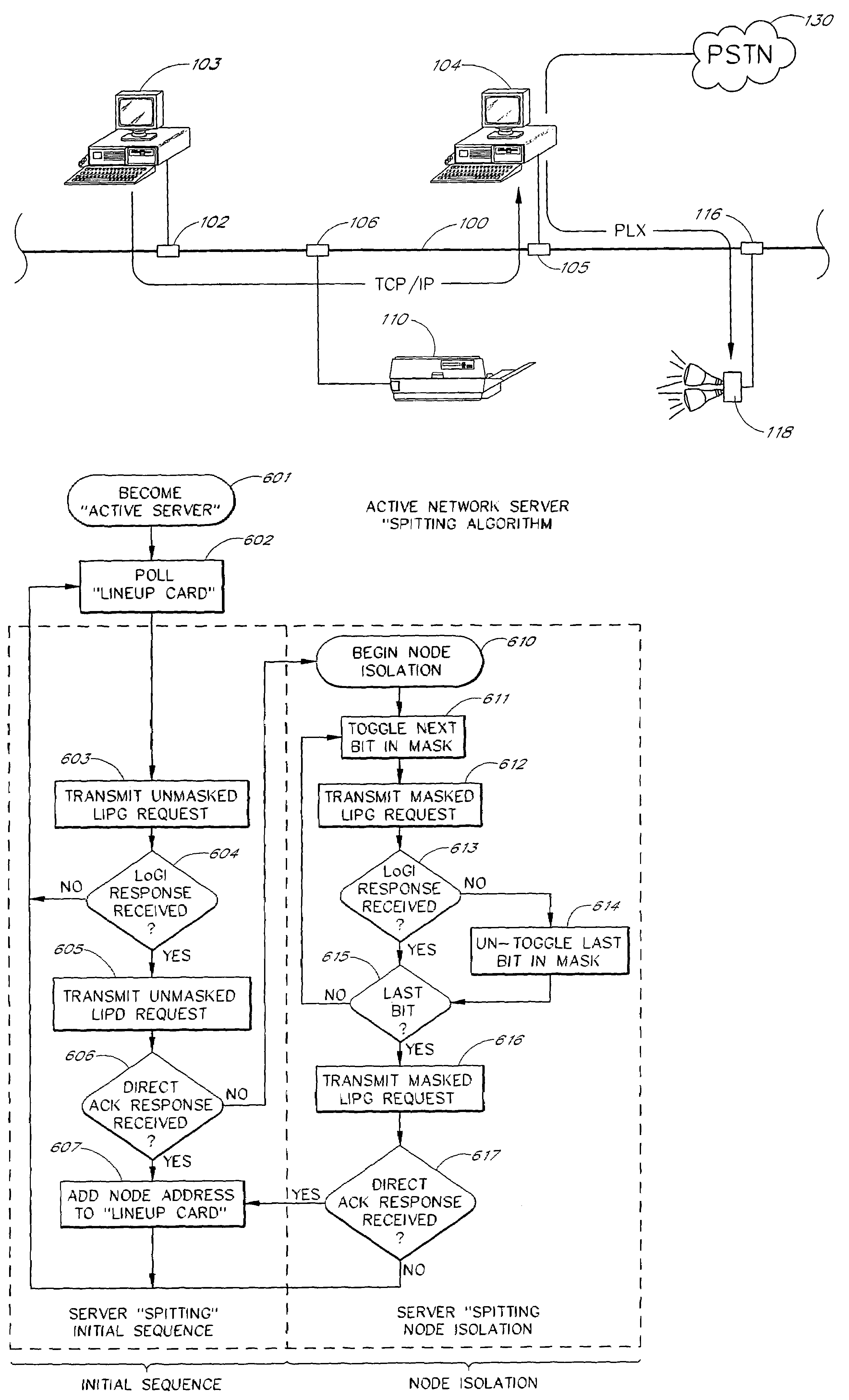
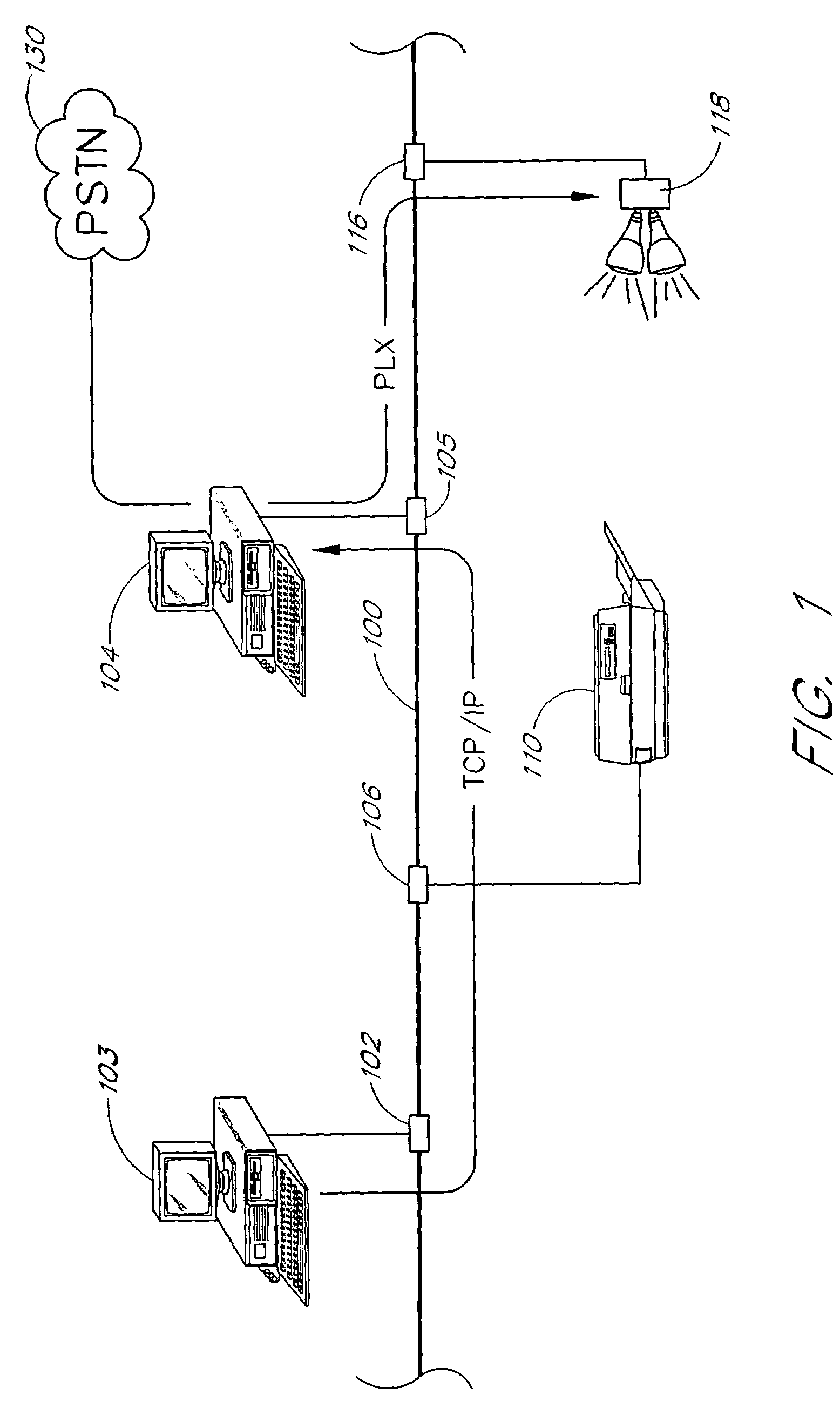
[0077]FIG. 1 shows a typical computer network having a network medium 100 (shown as a cable). A smart node (shown as a personal computer 103) is connected to the network medium 100 by a connector 102. A printer 110, a computer 104 and a security lighting system 118 are also connected to the network medium 100. The lighting system 118 is an example of a “dumb” node that has relatively little computing power or storage.

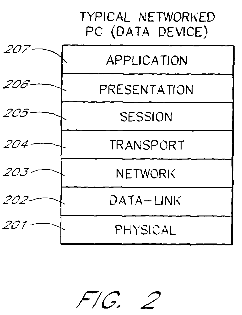
[0078]Most networks configured for smart nodes (such as the computers 103 and 104) are based on a network architecture model developed by the Open System Interface (OSI) committee. The OSI architecture defines a network model that outlines each individual hardware and software layer within a communication system, the inter-dependencies between layers, and the unique function each layer performs.

[0079]FIG. 2 shows the OSI architecture is split between seven layers, from lowest to highest: a physical layer 201; a data link layer 202; a network layer 203; a transport layer...


PUM


Abstract

A scalable networking protocol that allows multiple nodes to communicate via a multi-channel network medium is described. The networking protocol allows any node on the network to assign itself as the active network server. The active network server polls client nodes based on a lineup card. The lineup card includes a high priority queue for low-latency devices, and a low priority queue for devices that can tolerate higher latencies. Network information is sent on the channels as fragments. The protocol provides bad-channel detection and retransmission of fragments in a fragment-by-fragment basis. Support for streaming data or asynchronous data is provided by allocating time slots on the network and allowing two intelligent nodes to talk directly to each other during count-limited token sessions, as arbitrated by the active network server. The network node serving as the active network server can be changed on a dynamic basis, and is typically determined by the first node initiating a transmit request on a sleeping network. Client nodes are addressed by dynamic-polling using an address isolation scheme.

Description

BACKGROUND OF THE INVENTION[0001]1. Field of the Invention[0002]The disclosed invention relates to data network protocols, and more specifically, to protocols adapted to multi-channel and isochronous networking systems.[0003]2. Description of the Related Art[0004]The widespread availability of computers, especially personal computers, has generated a rapid increase in the number of computer networks. Networking two or more computers together allows the computers to share information, file resources, printers, etc. Connecting two or more personal computers and printers together to form a network is, in principle, a simple task. The computers and printers are simply connected together using a cable, and the necessary software is installed onto the computers. In network terminology, the cable is the network medium and the computers and printers are the network nodes. Unfortunately, in practice, creating a computer network is often not quite as simple as it sounds. Typically, a user wil...

Claims


Application Information

Patent Timeline
Patent Type & Authority Patents(United States)
IPC IPC(8): G06F15/173H04L1/00H04L1/16H04L1/18H04L12/28H04L12/403H04L12/56
CPCH04B3/54H04L1/1628H04L12/403H04B2203/5408H04B2203/5445H04L1/1809H04W74/0816H04L2001/0096H04W28/04H04W28/065H04W72/0446H04L12/4015
Inventor WALBECK, ALAN K.MILLER, MICHAEL J.SOUTHAM, ERIC R.GILES, BRADLEY C.
Owner INARI
Why Eureka
Try Eureka