Method and apparatus for link error prediction in a communication system

a communication system and error prediction technology, applied in the field of communication systems, can solve problems such as degrading the quality of the communication link, and affecting the accuracy of the transmission of signals

Inactive Publication Date: 2005-08-18
LUCENT TECH INC
View PDF2 Cites 17 Cited by
  • Summary
  • Abstract
  • Description
  • Claims
  • Application Information

AI Technical Summary

Problems solved by technology

A mobile device may for example suddenly move to a region where interference may quickly but temporarily degrade the quality of the communications link.
The changes in the quality of the link may mean that the receiver does not accurately receive some or all of the transmitted signals.
Consequently, some or all of the information contained within one or more frames may be degraded and it may or may not be possible to recover the transmitted information with the error control mechanisms and (re)transmission strategies that are in use.
Quick and accurate estimation of the link error probability has proven somewhat problematic.
The analyses typically involve decoding the frame to retrieve and check the information, which requires a significant amount of computing power and inherently results in delays.
To ensure accuracy, these analyses can take considerable time, which may make the communications relatively unresponsive.
For example, when transmitting voice signals, a significant lapse in the time between receiving the frame and detecting that it is in error may make it impossible to adapt the methods to improve the transmission in a timely fashion.
On the other hand, if the analyses are faster but less rigorous, frames may well be considered uncorrectable when in fact they can be corrected.
With less rigorous analyses, the link error probability will be quite unreliable and not useful for adaptive control algorithms.

Method used


Image

  • Method and apparatus for link error prediction in a communication system
  • Method and apparatus for link error prediction in a communication system
  • Method and apparatus for link error prediction in a communication system

Examples


Embodiment Construction

[0021] Illustrative embodiments of the invention are described below. In the interest of clarity, not all features of an actual implementation are described in this specification. It will of course be appreciated that in the development of any such actual embodiment, numerous implementation-specific decisions must be made to achieve the developers' specific goals, such as compliance with system-related and business-related constraints, which will vary from one implementation to another. Moreover, it will be appreciated that such a development effort might be complex and time-consuming, but would nevertheless be a routine undertaking for those of ordinary skill in the art having the benefit of this disclosure.

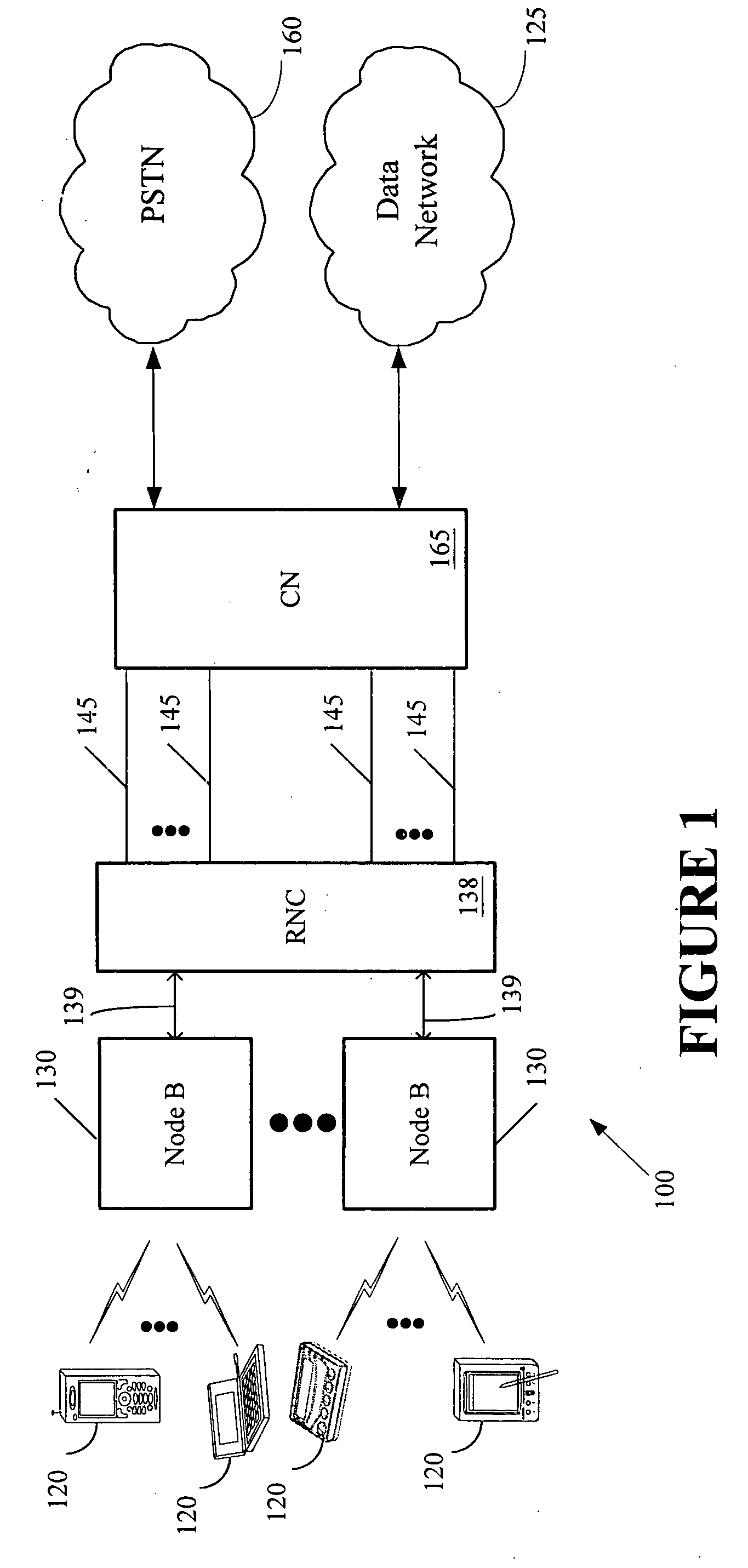
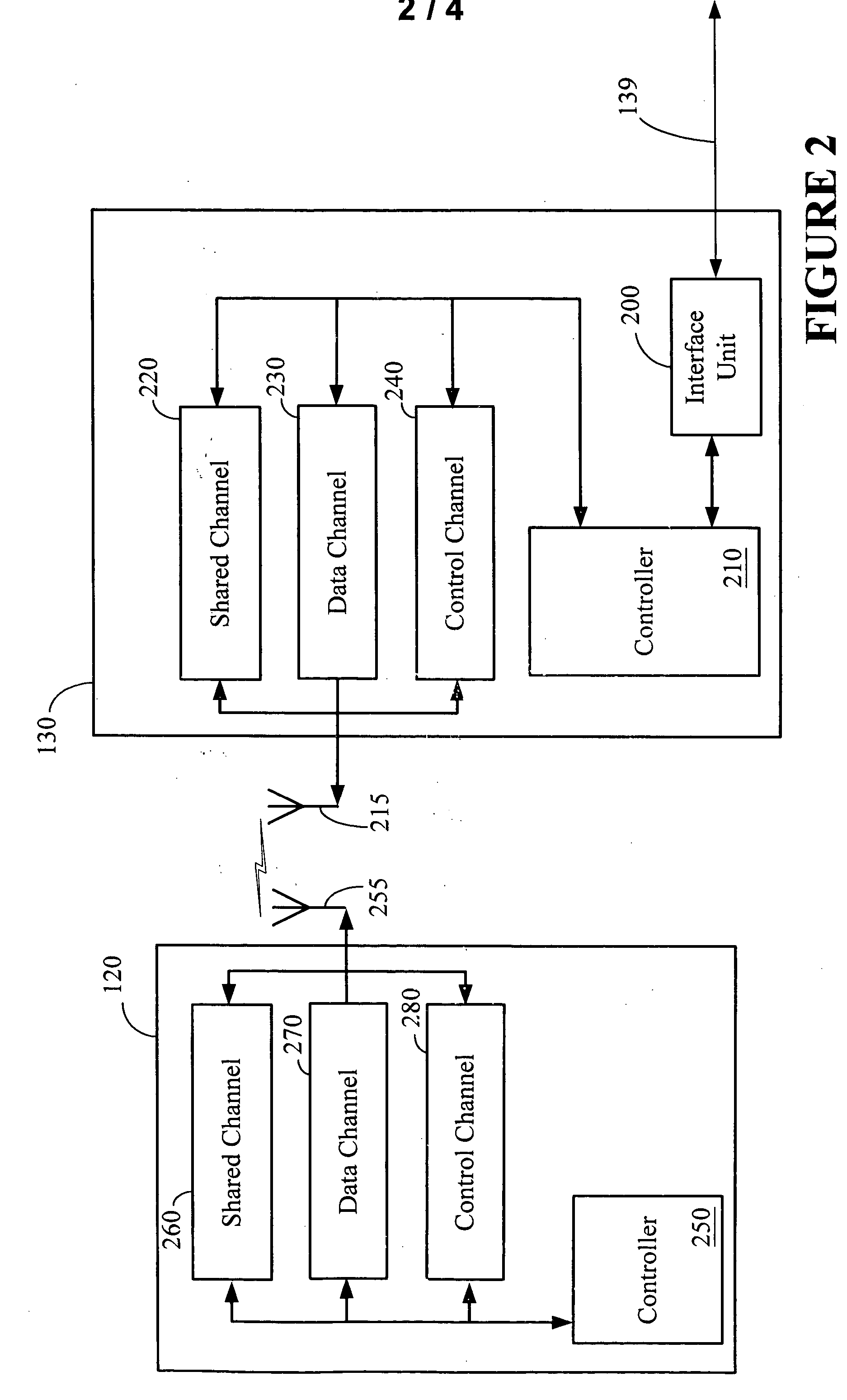
[0022] Turning now to the drawings, and specifically referring to FIG. 1, a communications system 100 is illustrated, in accordance with one embodiment of the present invention. For illustrative purposes, the communications system 100 of FIG. 1 may be a 1xEV-DO system, although...


PUM


Abstract

A method is provided to accurately predict the probability of successfully recovering frames of (coded) information received over a wireless link, without having to decode the frame. This method, which consists of three steps, requires only limited information about the received signals and the forward error correction code and retransmission scheme being used. First, the signal to noise ratio (SNR) of each of the received signals is measured, where the average SNR is determined for multiple segments that together constitute the frame. Next, an algorithm is employed that takes these SNR values as inputs and determines the so-called effective SNR. The algorithm translates the measured SNR values using an appropriate convex metric, and subsequently combines the resulting values, thereby factoring in the effects of fading, multi-path, and other signal degradations. In the third stage, the effective SNR is used to determine the frame error rate by using a look-up table of a single reference curve that specifies the frame error rate of the actual error control code over an additive white Gaussian noise channel. This suffices to accurately predict the performance of a wide range of mobile communication channels. This method can be applied to a variety of retransmission strategies, including hybrid automatic-repeat request (ARQ) and incremental redundancy (IR) and combinations of these two strategies.

Description

BACKGROUND OF THE INVENTION [0001] 1. Field of the Invention [0002] This invention relates generally to a communications system, and, more particularly to a method for predicting the probability of successfully recovering frames of (coded) information received over a communications link. [0003] 2. Description of the Related Art [0004] In a typical wireless communications session, information is transmitted to and from a mobile device over one or more links or channels with the information being grouped into segments or frames. A frame is a basic timing interval in the system and at the same time, a frame refers to the sequence of contiguous bits that represents the user and control information that is transmitted during this basic timing interval. A frame typically consists of one or several slots, the latter being the channel's unit time interval. In some applications, the frame duration and the signaling rate may vary substantially, depending, among other things, on the channel co...

Claims


Application Information

Patent Timeline
Patent Type & Authority Applications(United States)
IPC IPC(8): H03M13/47H04L1/16H04L1/18H04L1/20
CPCH04L1/1819H04L1/20H04L1/1845E03B3/15E03B3/16
Inventor ASHIKHMIN, ALEXEIVAN WIJNGAARDEN, ADRIAAN J. DE LINDGOPALAKRISHNAN, NANDUKIM, JAEHYEONGSOLJANIN, EMINA
Owner LUCENT TECH INC
Why Eureka
Try Eureka