Pressure sensor for detecting pressure by using capacitance variation according to deflection of diaphragm

a technology of capacitance variation and pressure sensor, which is applied in the direction of fluid pressure measurement using capacitance variation, fluid pressure measurement using elastically deformable gauges, instruments, etc., can solve the problem of limited capacitance lowering, the inability to reduce the capacitance to the initial measurement pressure, and the difficulty of increasing the variation amount in the measured range. , to achieve the effect of reducing the capacitance, increasing the distance between the fixed electrode and the portion of the dia

Inactive Publication Date: 2005-08-25
ALPS ALPINE CO LTD
View PDF1 Cites 43 Cited by
  • Summary
  • Abstract
  • Description
  • Claims
  • Application Information

AI Technical Summary

Benefits of technology

[0020] As mentioned above, the pressure sensor of the present invention comprises a base, a fixed electrode provided on a surface of the base, an insulating layer laminated on a fixed electrode to cover the fixed electrode, and a conductive diaphragm disposed to face the fixed electrode with a predetermined gap above the insulating layer. The pressure sensor detects a variation of a capacitance of the fixed electrode by a deflection of the diaphragm when a pressure is applied to the diaphragm. A protrusion protruding toward the diaphragm is formed on the insulating layer. Thereby, the distance between the fixed electrode and the portion which the diaphragm comes in contact with the insulating layer can be increased. Thus, the capacitance to the initial measurement pressure when the pressure measurement is started in a state in which the diaphragm comes in contact with the insulating layer can be lowered.
[0021] Further, since the protrusion is disposed at a location which is almost at the center of the fixed electrode, the center of the diaphragm which is first deflected upon application of a pressure securely comes in contact with the protrusion provided at the center of the fixed electrode. Thus, the capacitance to the initial measurement pressure can be lowered.
[0

Problems solved by technology

However, in the conventional pressure sensor for measuring the pressure in a state in which the diaphragm is brought in contact with the dielectric film, there is a problem in that the capacitance to the initi

Method used


Image

  • Pressure sensor for detecting pressure by using capacitance variation according to deflection of diaphragm
  • Pressure sensor for detecting pressure by using capacitance variation according to deflection of diaphragm
  • Pressure sensor for detecting pressure by using capacitance variation according to deflection of diaphragm

Examples


second embodiment

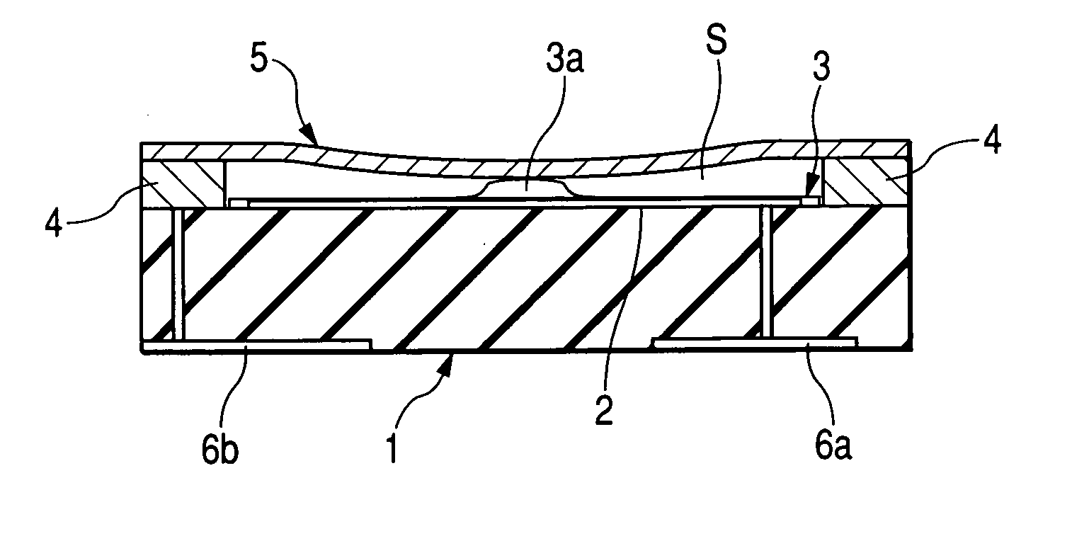
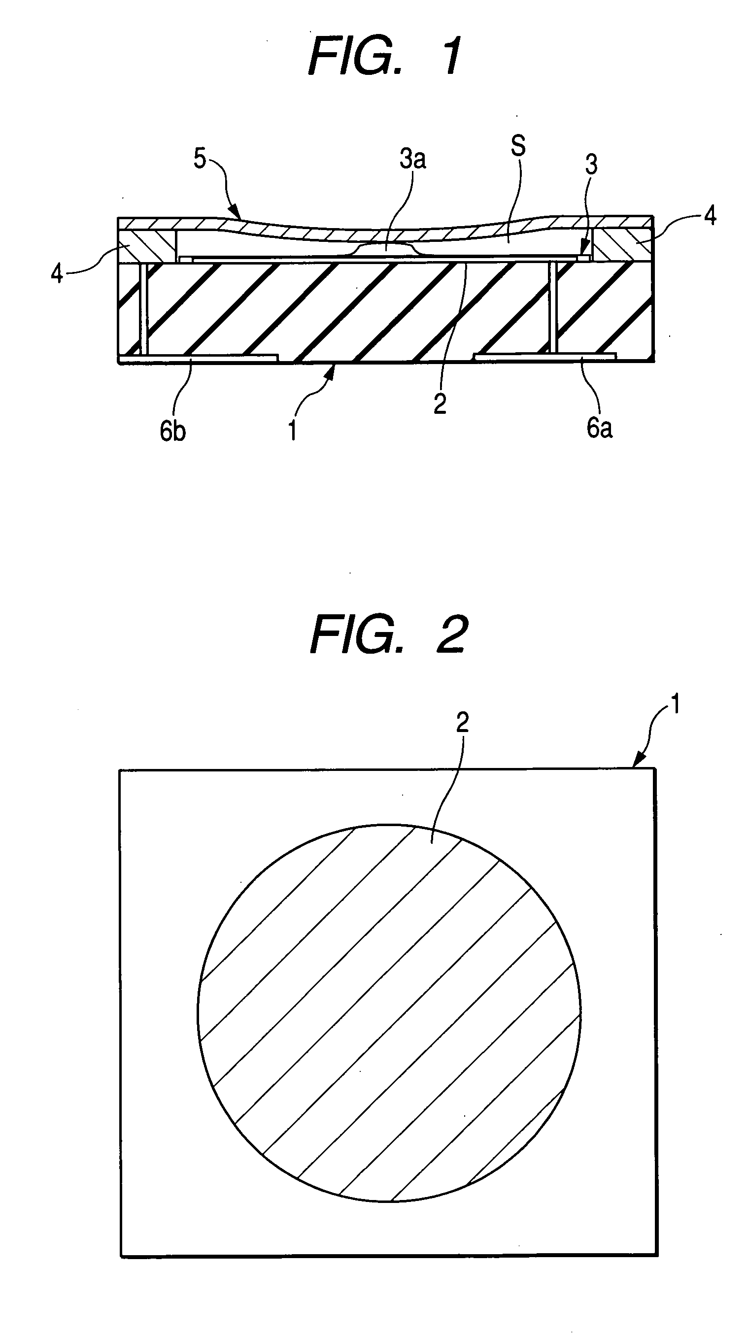
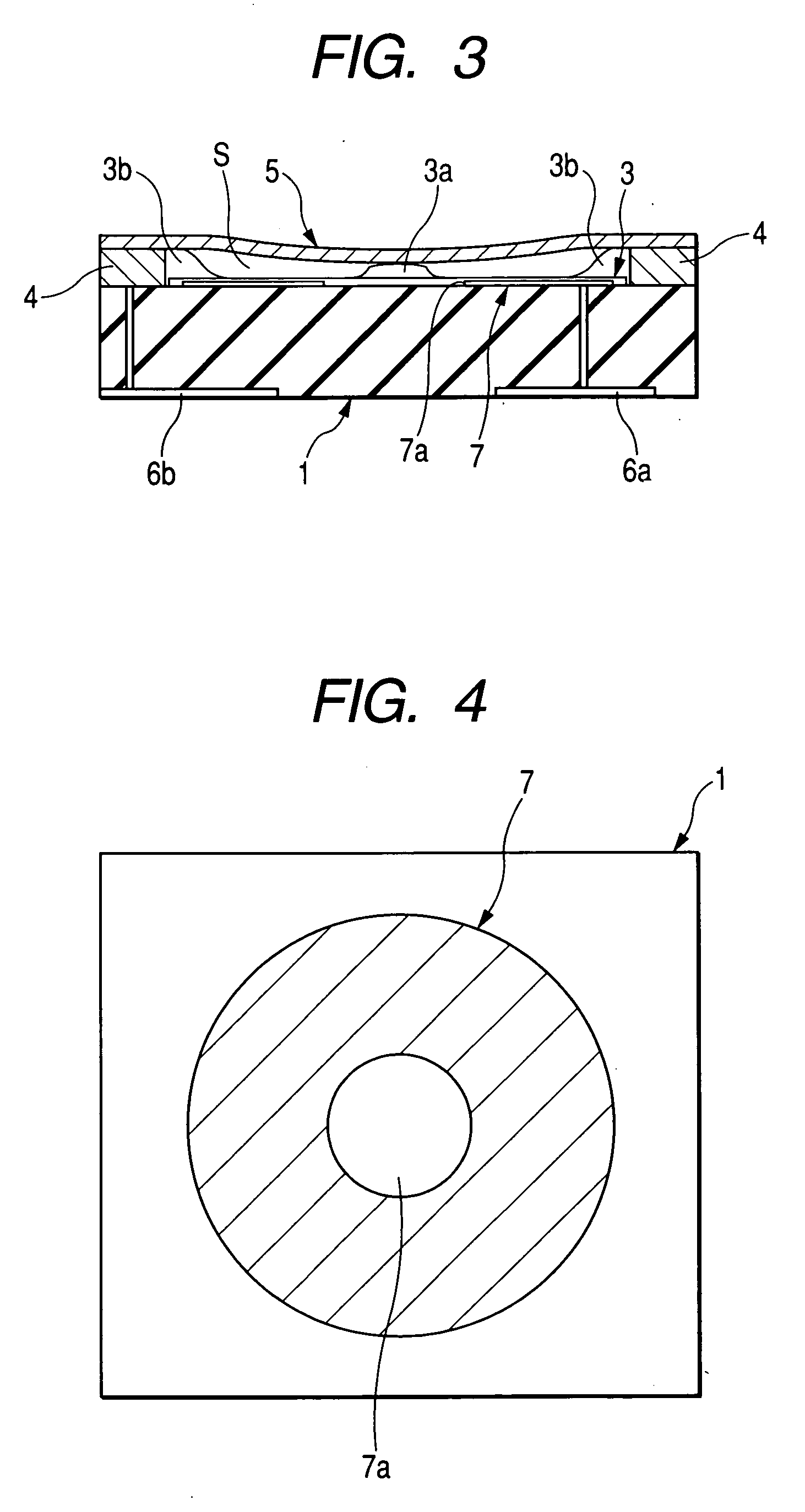
[0049]FIGS. 3 and 4 show the present invention.

[0050] In the present embodiment, the structure of the fixed electrode is partially different from that of the first embodiment. The same components as those of the first embodiment are denoted by the same reference numerals, and the detailed description thereof will be omitted.

[0051] In other words, the structure of the present embodiment is the same as that of the first embodiment in that the upwardly protruding protrusion 3a is formed at a position which is almost at the center of the fixed electrode. However, the fixed electrode 7 of the present embodiment is formed at the center thereof with a cutout portion 7a with respect to a portion with which the diaphragm comes in contact, as shown in FIG. 4. Further, the insulating layer 3 is also formed within the cutout portion 7a, and the protrusion 3a is formed above the cutout portion 7a.

[0052] As described above, in the present embodiment, since the cutout portion 7a is formed at the...

third embodiment

[0054]FIGS. 5 and 6 show the present invention.

[0055] In the present embodiment, the structure of the cutout portion formed at the fixed electrode is partially different from that of the second embodiment. The same components as those of the first and second embodiments are denoted by the same reference numerals, and the detailed description thereof is omitted.

[0056] In other words, the structure of the present embodiment is the same as those of the first and second embodiments in that the upwardly protruding protrusion 3a is formed at a position which is almost at the center of the fixed electrode. However, the fixed electrode 8 of the present embodiment is formed at the center thereof with a cutout portion 8a having a star-shaped through-hole having a plurality of sharpened portions provided radially from the center toward the periphery, with respect to a portion with which the diaphragm 5 comes in contact, as shown in FIG. 6. Further, the insulating layer 3 is formed within the ...


PUM


Abstract

A pressure sensor includes a base, a fixed electrode provided on the surface of the base, an insulating layer laminated on the fixed electrode to cover the fixed electrode, and a conductive diaphragm which is disposed to face the fixed electrode with a predetermined gap above the insulating layer. The pressure sensor detects a variation of a capacitance between the fixed electrode and the diaphragm by a deflection of the diaphragm when a pressure is applied to the diaphragm. A protrusion 3a protruding toward the diaphragm is formed on the insulating layer.

Description

BACKGROUND OF THE INVENTION [0001] 1. Field of the Invention [0002] The present invention relates to a structure of a pressure sensor for detecting pressure using a capacitance variation according to the deflection of a diaphragm. [0003] 2. Description of the Related Art [0004] A structure of a conventional pressure sensor is known. Such a pressure sensor generally includes a diaphragm having a conductive surface, an electrode formed of a metal film, and a base body provided with a dielectric film for covering an upper side thereof, in which the diaphragm and the electrode face each other and are bonded to each other with a gap between the diaphragm and the dielectric film (for example, see Japanese Unexamined Patent Application Publication No. 2002-195903). [0005] Hereinafter, the structure of the conventional pressure sensor will be explained with reference to the drawings. [0006]FIG. 9 shows the conventional pressure sensor, in which FIG. 9A is a plan view of the pressure sensor,...

Claims


Application Information

Patent Timeline
IPC IPC(8): G01L9/12G01L1/14G01L7/08G01L9/00
CPCG01L9/0072G01L1/142
Inventor SATO, HIDEAKI
Owner ALPS ALPINE CO LTD
Why Eureka
Try Eureka